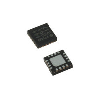
LDS8141-002-T2 IXYS, LDS8141-002-T2 Datasheet - Page 15

LDS8141-002-T2
Manufacturer Part Number
LDS8141-002-T2
Description
IC LED DRIVER WHIT BCKLGT 16WQFN
Manufacturer
IXYS
Series
LED-Sense™, Power-Lite™r
Type
Backlight, White LED (I²C Interface)r
Datasheet
1.LDS8141-002-T2.pdf
(22 pages)
Specifications of LDS8141-002-T2
Topology
High Side, Linear (LDO), PWM
Number Of Outputs
4
Internal Driver
Yes
Type - Primary
Backlight
Type - Secondary
White LED
Frequency
1.2MHz
Voltage - Supply
2.5 V ~ 5.5 V
Mounting Type
Surface Mount
Package / Case
16-WQFN, 16-miniQFN
Operating Temperature
-40°C ~ 85°C
Current - Output / Channel
32mA
Internal Switch(s)
Yes
Efficiency
80%
Lead Free Status / RoHS Status
Lead free / RoHS Compliant
Voltage - Output
-
Lead Free Status / Rohs Status
Details
Other names
LDS8141-002-T2-2
LDS8161/41
Unused LED Channels
For applications with less than six (8161) or four
(8141) LEDs, the unused LED channels can be
disabled via the I
03h
combination of LEDs turned ON/OFF (see Table 1).
The LDS8161/41 unused LED outputs can be left
open.
Parallel-Connected LED Channels for Higher
Current LEDs
In higher power LED applications requiring more than
31.875 mA DC current, LED driver channels can be
connected in parallel.
For example, ½ watt, 150 mA LEDs can be driven
with the LDS8161 by paralleling all 6 channels with
25 mA per channel. Likewise, the LDS8141 can drive
up to 127.5 mA by connecting all 4 channels in
parallel at the maximum 31.875 mA per channel.
LED short/open protection
The LDS8161/41 runs a LED short/open diagnostic
routine upon the power up sequence. It detects both
LED pins shorted to ground and LED pins that are
open or shorted to V
The results for short to GND detection are stored in
Diagnostics Register 1Ch. Bits from bit 5 to bit 0
indicate a short status as bit = 1 for LEDC2 - LEDA1
respectively. A short to GND is detected, if the
measured LED pin voltage is less than ~ 0.14 V
independent of the programmed LED current. Every
channel, detected as shorted, is disabled
Test results for open or short to V
stored in Diagnostics Register 1Dh, Bits from bit 5 to
bit 0 represent LEDC2 - LEDA1 respectively with bit
= 1 indicates fault condition at this particular LED pin.
An open LED pin fault causes no harm in the
LDS8161/41 or the LED as the high side driver has
no current path from V
detection status indicates only in the 1Dh diagnostic
register, and no further action is required.
In the case of an LED directly shorted to V
V
can flow independent of the LDS8161/41 LED driver
circuit directly to GND. The LDS8161/41 will detect
the fault and indicate the status in Register 1Dh,
however further action needs taken at the system
© 2009 IXYS Corp.
Characteristics subject to change without notice
IN
voltage will be connected to the LED and current
with
data
2
C interface by addressing register
that
IN
(fault conditions).
IN
or GND. Therefore, the fault
represents
IN
LED pins are
the
IN
, the full
desired
15
level to shutdown V
damage to the LED. The combined series resistance
of the LED (typically ~ 10Ω or more) and additional
board series resistance will result in current limiting
but not sufficient to insure no damage to low power
LEDs.
Besides the power-up diagnostic sequence, the user
can re-initiate a diagnostic command at any time by
setting bit 5 of the Digital Test Modes Register, 19h,
to HIGH.
The
programmed value at channels with detected shorts
to GND after the fault condition is removed.
Over-Temperature Protection
If the die temperature exceeds +150°C, the driver will
enter shutdown mode. The LDS8161/41 requires
restart after die temperature falls below 130°C.
LED Selection
If the power source is a Li-ion battery, LEDs with V
1.9 V - 3.3 V are recommended to achieve highest
efficiency performance and extended operation on a
single battery charge.
External Components
The driver requires one external 1 µF ceramic capa-
citors (C
CONFIGURATION MODES
The LDS8161/41 allows the option to choose special
operating modes overwriting content of Configuration
Register 1Eh (see Table 2).
Bit 1 allows bypass soft start / ramp down if fast
raising/falling LED current required.
Bit 2 allows disable LED temperature compensation if
desired.
The LDS8161/41 also provides the option for using
an external remote temperature-sensing diode device
such as a 2N3904. To use this option the diode
anode should be connected to channel LEDA1. The
cathode connected to GND. In this case, channel
LEDA1 should be disabled via register 03h and it
cannot operate as an LED current source.
Bits 0, 3, 4, 5, 6, and 7 of the Configuration Register
1Eh are for factory use only and should be set to 0 or
the user should use the power-on-reset values.
LDS8161/41
IN
) X5R or X7R type.
IN
restores
power to prevent possible
Doc. No. 8141/61_DS, Rev. N1.0
LED
current
F
to
=


