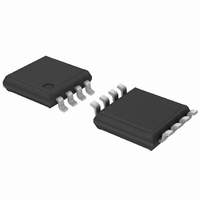
PCA9632DP1,118 NXP Semiconductors, PCA9632DP1,118 Datasheet - Page 11

PCA9632DP1,118
Manufacturer Part Number
PCA9632DP1,118
Description
IC LED DRIVER RGBA 8-TSSOP
Manufacturer
NXP Semiconductors
Type
RGBA LED Driverr
Datasheet
1.PCA9632TK118.pdf
(38 pages)
Specifications of PCA9632DP1,118
Package / Case
8-TSSOP
Topology
Open Drain, PWM
Number Of Outputs
4
Internal Driver
Yes
Type - Primary
Backlight, LED Blinker
Type - Secondary
RGBA
Frequency
1MHz
Voltage - Supply
2.3 V ~ 5.5 V
Voltage - Output
5.5V
Mounting Type
Surface Mount
Operating Temperature
-40°C ~ 85°C
Current - Output / Channel
25mA
Internal Switch(s)
Yes
Number Of Segments
4
Low Level Output Current
100000 uA
Operating Supply Voltage
2.3 V to 5.5 V
Maximum Supply Current
150 uA
Maximum Power Dissipation
400 mW
Maximum Operating Temperature
+ 85 C
Mounting Style
SMD/SMT
Minimum Operating Temperature
- 40 C
Lead Free Status / RoHS Status
Lead free / RoHS Compliant
Efficiency
-
Lead Free Status / Rohs Status
Lead free / RoHS Compliant
Other names
935284899118
PCA9632DP1-T
PCA9632DP1-T
PCA9632DP1-T
PCA9632DP1-T
Available stocks
Company
Part Number
Manufacturer
Quantity
Price
Part Number:
PCA9632DP1,118
Manufacturer:
NXP/恩智浦
Quantity:
20 000
NXP Semiconductors
Table 6.
Legend: * default value.
[1]
[2]
Table 7.
Legend: * default value.
[1]
[2]
PCA9632_3
Product data sheet
Bit
7
6
5
4
3
2
1
0
Bit
7
6
5
4
3
2
1 to 0
It takes 500 s max. for the oscillator to be up and running once SLEEP bit has been set to logic 0. Timings on LEDn outputs are not
guaranteed if PWMx, GRPPWM or GRPFREQ registers are accessed within the 500 s window.
When the oscillator is off (Sleep mode), the LED outputs cannot be turned on, off or dimmed/blinked.
See
mode. Some newer LEDs include integrated Zener diodes to limit voltage transients, reduce EMI, protect the LEDs, and these must be
driven only in the open-drain mode to prevent overheating the IC.
Change of the outputs at the STOP command allows synchronizing outputs of more than one PCA9632. Applicable to registers from
02h (PWM0) to 08h (LEDOUT) only.
Section 7.6 “Using the PCA9632 with and without external drivers”
Symbol
-
-
DMBLNK
INVRT
OCH
OUTDRV
OUTNE[1:0]
Symbol
AI2
AI1
AI0
SLEEP
SUB1
SUB2
SUB3
ALLCALL
MODE1 - Mode register 1 (address 00h) bit description
MODE2 - Mode register 2 (address 01h) bit description
[1]
7.3.1 Mode register 1, MODE1
7.3.2 Mode register 2, MODE2
[1]
Access
read only
read only
R/W
R/W
R/W
R/W
R/W
Access
read only
read only
read only
R/W
R/W
R/W
R/W
R/W
Value
0*
0*
0*
1
0*
1
0*
1
0*
1
01*
Value
0
1*
0*
1
0*
1
0
1*
0*
1
0*
1
0*
1
0
1*
Description
reserved
reserved
Group control = dimming
Group control = blinking
Output logic state not inverted. Value to use when no external driver used.
Output logic state inverted. Value to use when external driver used.
Outputs change on STOP command.
Outputs change on ACK.
The 4 LED outputs are configured with an open-drain structure.
The 4 LED outputs are configured with a totem pole structure.
unused
Rev. 03 — 15 July 2008
Description
Register Auto-Increment disabled
Register Auto-Increment enabled
Auto-Increment bit 1 = 0
Auto-Increment bit 1 = 1
Auto-Increment bit 0 = 0
Auto-Increment bit 0 = 1
Normal mode
Low power mode. Oscillator off
PCA9632 does not respond to I
PCA9632 responds to I
PCA9632 does not respond to I
PCA9632 responds to I
PCA9632 does not respond to I
PCA9632 responds to I
PCA9632 does not respond to LED All Call I
PCA9632 responds to LED All Call I
[1]
.
for more details. Normal LEDs can be driven directly in either
2
2
2
C-bus subaddress 1.
C-bus subaddress 2.
C-bus subaddress 3.
4-bit Fm+ I
[2]
2
2
2
[2]
C-bus subaddress 1.
C-bus subaddress 2.
C-bus subaddress 3.
.
2
C-bus address.
2
C-bus low power LED driver
2
C-bus address.
PCA9632
© NXP B.V. 2008. All rights reserved.
11 of 38


