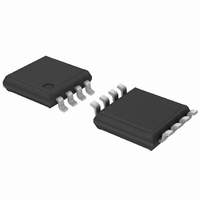
PCA9632DP1,118 NXP Semiconductors, PCA9632DP1,118 Datasheet - Page 9

PCA9632DP1,118
Manufacturer Part Number
PCA9632DP1,118
Description
IC LED DRIVER RGBA 8-TSSOP
Manufacturer
NXP Semiconductors
Type
RGBA LED Driverr
Datasheet
1.PCA9632TK118.pdf
(38 pages)
Specifications of PCA9632DP1,118
Package / Case
8-TSSOP
Topology
Open Drain, PWM
Number Of Outputs
4
Internal Driver
Yes
Type - Primary
Backlight, LED Blinker
Type - Secondary
RGBA
Frequency
1MHz
Voltage - Supply
2.3 V ~ 5.5 V
Voltage - Output
5.5V
Mounting Type
Surface Mount
Operating Temperature
-40°C ~ 85°C
Current - Output / Channel
25mA
Internal Switch(s)
Yes
Number Of Segments
4
Low Level Output Current
100000 uA
Operating Supply Voltage
2.3 V to 5.5 V
Maximum Supply Current
150 uA
Maximum Power Dissipation
400 mW
Maximum Operating Temperature
+ 85 C
Mounting Style
SMD/SMT
Minimum Operating Temperature
- 40 C
Lead Free Status / RoHS Status
Lead free / RoHS Compliant
Efficiency
-
Lead Free Status / Rohs Status
Lead free / RoHS Compliant
Other names
935284899118
PCA9632DP1-T
PCA9632DP1-T
PCA9632DP1-T
PCA9632DP1-T
Available stocks
Company
Part Number
Manufacturer
Quantity
Price
Part Number:
PCA9632DP1,118
Manufacturer:
NXP/恩智浦
Quantity:
20 000
NXP Semiconductors
PCA9632_3
Product data sheet
Table 4.
Remark: Other combinations not shown in
reserved and must not be used for proper device operation.
AI[2:0] = 000 is used when the same register must be accessed several times during a
single I
is overwritten each time the register is accessed during a write operation.
AI[2:0] = 100 is used when all the registers must be sequentially accessed, for example,
power-up programming.
AI[2:0] = 101 is used when the four LED drivers must be individually programmed with
different values during the same I
setting to another color setting.
AI[2:0] = 110 is used when the LED drivers must be globally programmed with different
settings during the same I
blinking change.
AI[2:0] = 111 is used when individual and global changes must be performed during the
same I
same time.
Only the 4 least significant bits D[3:0] are affected by the AI[2:0] bits.
When the Control register is written, the register entry point determined by D[3:0] is the
first register that will be addressed (read or write operation), and can be anywhere
between 0000 and 1100 (as defined in
is set and the rollover value at which the point where the register increment stops and
goes to the next one is determined by AI[2:0]. See
example, if the Control register = 1110 1000 (E8h), then the register addressing sequence
will be (in hex):
08
as the master keeps sending or reading data.
AI2
0
1
1
1
1
…
2
2
C-bus communication, for example, changing a color and global brightness at the
AI1
0
0
0
1
1
C-bus communication, for example, changes the brightness of a single LED. Data
Auto-Increment options
0C
AI0
0
0
1
0
1
00
Function
no Auto-Increment
Auto-Increment for all registers. D3, D2, D1, D0 roll over to ‘0000’ after
the last register (1100) is accessed.
Auto-Increment for Individual brightness registers only. D3, D2, D1, D0
roll over to ‘0010’ after the last register (0101) is accessed.
Auto-Increment for global control registers only. D3, D2, D1, D0 roll over
to ‘0110’ after the last register (0111) is accessed.
Auto-Increment for individual and global control registers only. D3, D2,
D1, D0 roll over to ‘0010’ after the last register (0111) is accessed.
Rev. 03 — 15 July 2008
…
2
C-bus communication, for example, global brightness or
07
2
C-bus communication, for example, changing color
02
Table
…
Table 4
5). When AI[2] = 1, the Auto-Increment flag
4-bit Fm+ I
07
Table 4
(AI[2:0] = 001, 010, and 011) are
02
2
for rollover values. For
C-bus low power LED driver
…
07
PCA9632
© NXP B.V. 2008. All rights reserved.
02
… as long
9 of 38


