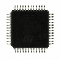
L6740LTR STMicroelectronics, L6740LTR Datasheet - Page 10

L6740LTR
Manufacturer Part Number
L6740LTR
Description
IC HYBRID CONTROLLERS 48TQFP
Manufacturer
STMicroelectronics
Datasheet
1.L6740LTR.pdf
(44 pages)
Specifications of L6740LTR
Applications
Hybrid Controllers
Voltage - Supply
9 V ~ 15 V
Current - Supply
20mA
Operating Temperature
0°C ~ 125°C
Mounting Type
Surface Mount
Package / Case
48-TQFP Exposed Pad, 48-eTQFP, 48-HTQFP, 48-VQFP
Number Of Outputs
2
Output Current
170 A
Input Voltage
13.2 V
Mounting Style
SMD/SMT
Maximum Operating Temperature
+ 125 C
Minimum Operating Temperature
0 C
Lead Free Status / RoHS Status
Lead free / RoHS Compliant
Voltage - Input
-
Lead Free Status / Rohs Status
Lead free / RoHS Compliant
Other names
497-6298-2
Available stocks
Company
Part Number
Manufacturer
Quantity
Price
Part Number:
L6740LTR
Manufacturer:
ST
Quantity:
20 000
Pins description and connection diagrams
10/44
Table 2.
25,
19
20
21
23
26
28
29
30
Pin#
22
24
27
Pin description (continued)
OC_PHASE
VID4, VID5
OSC / FLT
OC_AVG /
NB_ISEN
NB_FBG
NB_OS
Name
CS4+
CS4-
NC
NC
LI
Channel 4 current sense positive input. Connect through an R-C filter to
the phase-side of the channel 4 inductor. When working at 2 or 3
phase, directly connect to V
See
Channel 4 current sense negative input. Connect through a R
to the output-side of the channel inductor. When working at 2 or 3
phase, connect through R
See
Per-phase over-current (CORE section).
Internally set to 1.24 V, connecting to SGND with a resistor R
programs the OC threshold per-phase. See
Not internally connected.
NB current sense pin.
Used for NB voltage positioning and NB_OCP. Connect through a
resistor R
Not internally connected.
Voltage IDentification pins.
Internally pulled-low by 10 μA, they are used to program the output
voltage. Used only in PVI-mode, ignored when in SVI-mode.
See
OSC: It allows programming the switching frequency F
sections. Switching frequency can be increased according to the
resistor R
6.8 kHz/µA (see
frequency is 150 kHz per phase.
FLT: The pin is forced high (3.3 V) in case of an OV / UV fault. To
recover from this condition, cycle VCC or the EN pin. See
details.
Average over-current and load indicator pin.
A current proportional to the current delivered by the CORE section (a
copy of the DROOP current) is sourced through this pin.
The average-OC threshold is programmed by connecting a resistor
R
threshold (V
OFF (to recover, cycle VCC or the EN pin).
A load indicator with 2.5 V end-of-scale is then implemented.
See
Offset programming pin.
Internally set to 1.24 V, connecting a R
setting a current that is mirrored into NB_FB pin in order to program a
positive offset according to the selected R
disable the function. See
Remote ground sense.
Connect to the negative side of the load to perform remote sense. See
Section 9
OC_AVG
Section 9
Section 9
Section 5
Section 7.4.1
to SGND. When the generated voltage crosses the OC_AVG
ISEN
OSC
for proper layout of this connection.
OC_AVGTH
connected from the pin to. SGND with a gain of
to the relative LS Drain. See
for proper layout of this connection.
for proper layout of this connection.
for details.
Section 8
for details.
= 2.5 V Typ) the device latches with all mosfets
Section 6.7
G
for details). If floating, the switching
out_CORE
to CS4+.
Function
.
for details.
OS_NB
FB_NB
Section 7.4
Section 7.4.1
resistor to SGND allows
. Short to SGND to
SW
for details.
for details.
of both
Section 7
OC_TH
G
resistor
L6740L
it
for


