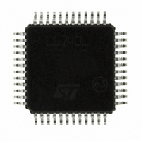
L6740LTR STMicroelectronics, L6740LTR Datasheet - Page 18

L6740LTR
Manufacturer Part Number
L6740LTR
Description
IC HYBRID CONTROLLERS 48TQFP
Manufacturer
STMicroelectronics
Datasheet
1.L6740LTR.pdf
(44 pages)
Specifications of L6740LTR
Applications
Hybrid Controllers
Voltage - Supply
9 V ~ 15 V
Current - Supply
20mA
Operating Temperature
0°C ~ 125°C
Mounting Type
Surface Mount
Package / Case
48-TQFP Exposed Pad, 48-eTQFP, 48-HTQFP, 48-VQFP
Number Of Outputs
2
Output Current
170 A
Input Voltage
13.2 V
Mounting Style
SMD/SMT
Maximum Operating Temperature
+ 125 C
Minimum Operating Temperature
0 C
Lead Free Status / RoHS Status
Lead free / RoHS Compliant
Voltage - Input
-
Lead Free Status / Rohs Status
Lead free / RoHS Compliant
Other names
497-6298-2
Available stocks
Company
Part Number
Manufacturer
Quantity
Price
Part Number:
L6740LTR
Manufacturer:
ST
Quantity:
20 000
Hybrid CPU support and CPU_TYPE detection
5.3
5.4
5.4.1
18/44
SVI - serial interface
SVI is a two wire, clock and data, bus that connects a single master (CPU) to one slave
(L6740L). The master initiates and terminates SVI transactions and drives the clock, SVC,
and the data, SVD, during a transaction. The slave receives the SVI transactions and acts
accordingly. SVI wire protocol is based on fast-mode I
SVI interface also considers two additional signal needed to manage the system start-up.
These signals are EN and PWROK. The device return a PWRGOOD signal if the output
voltages are in regulation.
SVI start-up
Once the SVI mode has been detected on the EN rising-edge, L6740L checks for the status
of the two serial VID pins, SVC and SVD, and stores this value as the Pre-PWROK Metal
VID. The controller initiate a soft-start phase regulating both CORE and NB voltage planes
to the voltage level prescribed by the Pre-PWROK Metal VID. See
Pre-PWROK Metal VID codifications. The stored Pre-PWROK Metal VID value are re-used
in any case of PWROK de-assertion.
After bringing the output rails into regulation, the controller asserts the PWRGOOD signal
and waits for PWROK to be asserted. Until PWROK is asserted, the Controller regulates to
the Pre-PWROK Metal VID ignoring any commands coming from the SVI interface.
After PWROK is asserted, the processor has initialized the serial VID interface and L6740L
waits for commands from the CPU to move the voltage planes from the Pre-PWROK Metal
VID values to the operative VID values. As long as PWROK remains asserted, the controller
will react to any command issued through the SVI interface according to SVI Protocol.
See
Table 7.
Set VID command
The Set VID Command is defined as the command sequence that the CPU issues on the
SVI bus to modify the voltage level of the CORE section and/or the NB section.
During a Set VID Command, the processor sends the start (START) sequence followed by
the address of the section which the Set VID Command applies. The processor then sends
the write (WRITE) bit. After the write bit, the Voltage Regulator (VR) sends the acknowledge
(ACK) bit. The processor then sends the VID bits code during the data phase. The VR
sends the acknowledge (ACK) bit after the data phase. Finally, the processor sends the stop
(STOP) sequence. After the VR has detected the stop, it performs an On-the-Fly VID
SVC
Section 6.10
0
0
1
1
V_FIX mode and metalVID
SVD
for details about soft-start.
0
1
0
1
Pre-PWROK metal VID
1.1V
1.0V
0.9V
0.8V
Output voltage [V]
2
C.
Table 7
V_FIX mode
1.4V
1.2V
1.0V
0.8V
for details about
L6740L


