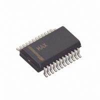
MAX8650EEG+ Maxim Integrated Products, MAX8650EEG+ Datasheet

MAX8650EEG+
Specifications of MAX8650EEG+
Related parts for MAX8650EEG+
MAX8650EEG+ Summary of contents
Page 1
... Adjustable Foldback Current Limit o Adjustable Slope Compensation o Selectable Current-Limit Mode: Latch-Off or Automatic Recovery o Monotonic Output-Voltage Rise at Startup o Output Sources and Sinks Current o Enable Input o Power-OK (POK) Output o Adjustable Soft-Start o Independently Adjustable Overvoltage Protection Applications PART MAX8650EEG+ + Denotes a lead-free/RoHS-compliant package FSYNC MODE BST 5 ...
Page 2
... REFIN INPUT REFIN Dual Mode™ Threshold REFIN Input Bias Current V REFIN REFIN Input Voltage Range Dual Mode is a trademark of Maxim Integrated Products, Inc. 2 _______________________________________________________________________________________ AVL, FB, POK, COMP, SS, MODE, REFIN to GND .....-0.3V to +6V CS+, CS- to GND .....................................................-0.3V to +6V + 0.3V) PGND to GND .......................................................-0.3V to +0.3V ...
Page 3
Input Current-Mode Step-Down Controller with Adjustable Frequency ELECTRICAL CHARACTERISTICS (continued 12V 6.5V -40°C to +85°C. Typical values are BST LX A PARAMETER ERROR AMPLIFIER REFIN = ...
Page 4
Input Current-Mode Step-Down Controller with Adjustable Frequency ELECTRICAL CHARACTERISTICS (continued 12V 6.5V -40°C to +85°C. Typical values are BST LX A PARAMETER FSYNC Synchronization Range FSYNC ...
Page 5
Input Current-Mode Step-Down Controller with Adjustable Frequency ELECTRICAL CHARACTERISTICS (continued 12V 6.5V -40°C to +85°C. Typical values are BST LX A PARAMETER POK REFIN = AVL, ...
Page 6
Input Current-Mode Step-Down Controller with Adjustable Frequency (Circuit of Figure 3, 500kHz switching, V EFFICIENCY vs. LOAD CURRENT 100 90 80 12V INPUT, 3.3V OUTPUT 70 12V INPUT, 2.5V OUTPUT 12V INPUT, 1.8V OUTPUT 60 24V INPUT, ...
Page 7
Input Current-Mode Step-Down Controller with Adjustable Frequency (Circuit of Figure 3, 500kHz switching, V POWER-UP WAVEFORMS MAX8650 toc09 V POK OUT I L 2ms/div SYNCHRONIZATION WAVEFORMS MAX8650 toc12 V FSYNC V SYNCO V DH ...
Page 8
Input Current-Mode Step-Down Controller with Adjustable Frequency PIN NAME Frequency Set and Synchronization. Connect a resistor from FSYNC to GND to set the switching 1 FSYNC frequency, or drive with an external clock signal between 160kHz and ...
Page 9
Input Current-Mode Step-Down Controller with Adjustable Frequency PIN NAME Output Voltage Sensing for Overvoltage Protection. Connect OVP to the center of a resistor-divider 17 OVP from OUT to GND to set the FB independent output overvoltage trip ...
Page 10
Input Current-Mode Step-Down Controller with Adjustable Frequency IN 6.5V LDO EN REGULATOR VL 5V AVL AVL LDO VOLTAGE REFERENCE REF SELECT LOGIC REFIN SS ERROR AMP GM FB COMP OVP CS CS- 10μA VL ILIM1 ...
Page 11
Input Current-Mode Step-Down Controller with Adjustable Frequency Detailed Description DC-DC Converter Control Architecture The MAX8650 step-down controller uses a PWM, cur- rent-mode control scheme. An internal transconduc- tance amplifier establishes an integrated error voltage. The heart of ...
Page 12
Input Current-Mode Step-Down Controller with Adjustable Frequency VL BST DH MAX8650 LX DL Figure 2. DH Boost Circuit to 20 squares (50 mils to 100 mils wide if the MOSFET is 1in from the device) for the ...
Page 13
Input Current-Mode Step-Down Controller with Adjustable Frequency ⎛ ⎞ ⎛ − R ⎜ 162 ns ⎟ ⎜ FSYNC ⎝ ⎠ ⎝ The MAX8650 can also be synchronized to an external clock by ...
Page 14
Input Current-Mode Step-Down Controller with Adjustable Frequency Table 1. Component List for Figure 3 COMPONENT C1, C2, C3 10µF, 25V X5R ceramic capacitors C5, C6 0.1µF, 10V X7R ceramic capacitors C7 220pF, 50V X7R ceramic capacitor C8 ...
Page 15
Input Current-Mode Step-Down Controller with Adjustable Frequency SYNC 1 FSYNC EN OPTIONAL OFF POK 24 POK SYNCO 3 SYNCO 23 SCOMP R5 22 ILIM2 REFIN V REFIN 0.9V ...
Page 16
Input Current-Mode Step-Down Controller with Adjustable Frequency Table 2. Component List for Figure 4 COMPONENT DESCRIPTION C1, C2 10µF, 16V X5R ceramic capacitors (1210) C3 0.01µF, 10V X7R ceramic capacitor (0603) C4, C5 0.1µF, 10V X7R ceramic ...
Page 17
Input Current-Mode Step-Down Controller with Adjustable Frequency TIME Figure 5. Inductor-Current Waveform Design Procedure Setting the Output Voltage To set the output voltage for the MAX8650, connect FB to the center of an external resistor-divider from the ...
Page 18
Input Current-Mode Step-Down Controller with Adjustable Frequency where f is the switching frequency. Choose a standard- S value inductor close to the calculated value. The exact inductor value is not critical and can be adjusted to make ...
Page 19
Input Current-Mode Step-Down Controller with Adjustable Frequency MAX8650 LX R4 CS+ CS- Figure 8. Current Sense Using the Inductor’s DC Resistance The DC resistance of the inductor’s copper wire has a +0.22%/°C temperature coefficient. To use the ...
Page 20
Input Current-Mode Step-Down Controller with Adjustable Frequency ⎛ ⎞ V OUT 2 = − ⎟ × P ⎜ LSCC LOAD ⎝ ⎠ Use DS(ON) J(MAX) = × × P ...
Page 21
Input Current-Mode Step-Down Controller with Adjustable Frequency I − RIPPLE × OUT where I is the peak-to-peak inductor current: P-P − OUT = × I ...
Page 22
Input Current-Mode Step-Down Controller with Adjustable Frequency GAIN CLOSE LOOP (dB) POWER MODULATOR f C 0dB f pMOD FB DIVIDER f zMOD Figure 10. Simplified Gain Plot for the f zMOD > Case The transconductance ...
Page 23
Input Current-Mode Step-Down Controller with Adjustable Frequency For the case where f is less than f zMOD The power modulator gain MOD MOD The ...
Page 24
Input Current-Mode Step-Down Controller with Adjustable Frequency Applications Information PCB Layout Guidelines Careful PCB layout is critical to achieve low switching losses and clean, stable operation. The switching power stage requires particular attention. Follow these guide- lines ...
Page 25
... Maxim cannot assume responsibility for use of any circuitry other than circuitry entirely embodied in a Maxim product. No circuit patent licenses are implied. Maxim reserves the right to change the circuitry and specifications without notice at any time. Maxim Integrated Products, 120 San Gabriel Drive, Sunnyvale, CA 94086 408-737-7600 ____________________ 25 © 2008 Maxim Integrated Products ...


