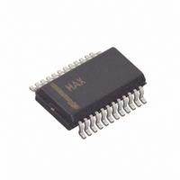
MAX8650EEG+ Maxim Integrated Products, MAX8650EEG+ Datasheet - Page 18

MAX8650EEG+
Manufacturer Part Number
MAX8650EEG+
Description
IC CNTRLR STP DWN 24-QSOP
Manufacturer
Maxim Integrated Products
Type
Step-Down (Buck)r
Datasheet
1.MAX8650EEG.pdf
(25 pages)
Specifications of MAX8650EEG+
Internal Switch(s)
No
Synchronous Rectifier
No
Number Of Outputs
1
Voltage - Output
0.7 ~ 5.5 V
Current - Output
25A
Frequency - Switching
200kHz ~ 1.2MHz
Voltage - Input
4.5 ~ 28 V
Operating Temperature
-40°C ~ 85°C
Mounting Type
Surface Mount
Package / Case
24-QSOP
Power - Output
762mW
Output Voltage
0.7 V to 5.5 V
Output Current
25 A
Input Voltage
4.5 V to 28 V
Mounting Style
SMD/SMT
Maximum Operating Temperature
+ 85 C
Minimum Operating Temperature
- 40 C
Lead Free Status / RoHS Status
Lead free / RoHS Compliant
4.5V to 28V Input Current-Mode Step-Down
Controller with Adjustable Frequency
where f
value inductor close to the calculated value. The exact
inductor value is not critical and can be adjusted to
make trade-offs between size, cost, and efficiency.
Lower inductor values minimize size and cost, but they
also increase the output ripple and reduce the efficiency
due to higher peak currents. On the other hand, higher
inductor values increase efficiency, but eventually resis-
tive losses due to extra turns of wire exceed the benefit
gained from lower AC current levels. This is especially
true if the inductance is increased without also increas-
ing the physical size of the inductor. Find a low-loss
inductor with the lowest possible DC resistance that fits
the allotted dimensions. Ferrite cores are often the best
choice, although powdered iron is inexpensive and can
work well at 300kHz. The chosen inductor’s saturation
current rating must exceed the peak inductor current
determined as:
The MAX8650 has an adjustable valley current limit,
configurable for foldback with automatic recovery, or a
constant-current limit with latchup. To set the current
limit for foldback mode, connect a resistor from ILIM2
to the output (R
to GND (R
and R
1) First, select the percentage of foldback (P
18
percentage corresponds to the current limit when
V
V
P
P
equations are used to calculate R
where I
at maximum load (I
R
MOSFET at the highest operating junction temperature.
R
OUT
OUT
FB
FB
DS(ON)
______________________________________________________________________________________
ILIM
ILIM2
S
I
is in the 15% to 40% range. A lower value of
yields lower short-circuit current. The following
PEAK
2
is the switching frequency. Choose a standard-
equals zero, divided by the current limit when
equals its nominal voltage. A typical value of
VALLEY
=
ILIM2
are calculated as follows:
is the maximum on-resistance of the low-side
5
V
R
OUT
×
=
FOBK
I
R
LOAD MAX
FOBK
). See Figure 7. The values of R
DS ON
is the value of the inductor valley current
−
(
⎡
⎣ ⎢
5
=
(
), and another resistor from ILIM2
×
)
5
Setting the Current Limit
R
×
μ
P
LOAD(MAX)
DS ON
FB
A
I
VALLEY
)
+
× −
(
×
(
LIR
1
2
V
)
OUT
×
P
×
× −
I
FB
VALLEY
Valley Current Limit
I
(
LOAD MAX
1
)
FOBK
- 1/2 x I
P
FB
(
× −
)
and R
(
×
1
R
)
FOBK
P-P
P
FB
FB
ILIM2
), and
). This
)
FOBK
⎤
⎦ ⎥
:
2) If the resulting value of R
The peak current-limit threshold (V
tor connected from ILIM1 to GND. V
the peak voltage across the sensing element (inductor
or current-sense resistor), R
as follows:
This allows a maximum DC output current (I
where R
the value of the optional current-sense resistor.
To ensure maximum output current, use the minimum
value of V
values at the highest expected operating temperature.
Figure 7. ILIM2 Resistor Connections
increase P
lower R
the efficiency and results in a lower short-cir-
cuit current.
To set the constant-current limit for the latchup
mode, only R
below sets the current-limit threshold at 1.2 times the
maximum rated output current:
Similarly, I
current at maximum load and R
mum on-resistance of the low-side MOSFET at the
highest operating junction temperature.
DC
MAX8650
TH
DS(ON)
is either the DC resistance of the inductor or
R
from each setting, and the maximum R
VALLEY
FB
ILIM
ILIM2
or choose a low-side MOSFET with a
. The latter is preferred as it increases
ILIM2
2
R
LX
I
LIM
=
ILIM
is the value of the inductor valley
1 2
is used. The equation for R
.
=
1
×
R
=
V
I
DC
TH
VALLEY
8
10
LIM1
×
ILIM2
−
V
μ
1
I
TH
μ
A
P P
. R
A
2
−
TH
×
Peak Current Limit
DS(ON)
is negative, either
R
TH
LIM1
) is set by a resis-
DS ON
corresponds to
(
R
R
FOBK
ILIM2
is calculated
OUT
LIM
is the maxi-
)
) of:
ILIM2
DC


