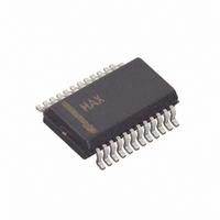
MAX8650EEG+ Maxim Integrated Products, MAX8650EEG+ Datasheet - Page 8

MAX8650EEG+
Manufacturer Part Number
MAX8650EEG+
Description
IC CNTRLR STP DWN 24-QSOP
Manufacturer
Maxim Integrated Products
Type
Step-Down (Buck)r
Datasheet
1.MAX8650EEG.pdf
(25 pages)
Specifications of MAX8650EEG+
Internal Switch(s)
No
Synchronous Rectifier
No
Number Of Outputs
1
Voltage - Output
0.7 ~ 5.5 V
Current - Output
25A
Frequency - Switching
200kHz ~ 1.2MHz
Voltage - Input
4.5 ~ 28 V
Operating Temperature
-40°C ~ 85°C
Mounting Type
Surface Mount
Package / Case
24-QSOP
Power - Output
762mW
Output Voltage
0.7 V to 5.5 V
Output Current
25 A
Input Voltage
4.5 V to 28 V
Mounting Style
SMD/SMT
Maximum Operating Temperature
+ 85 C
Minimum Operating Temperature
- 40 C
Lead Free Status / RoHS Status
Lead free / RoHS Compliant
4.5V to 28V Input Current-Mode Step-Down
Controller with Adjustable Frequency
8
_______________________________________________________________________________________
PIN
10
11
12
13
14
15
16
1
2
3
4
5
6
7
8
9
SYNCO
FSYNC
MODE
NAME
PGND
ILIM1
GND
CS+
BST
AVL
CS-
DH
DL
EN
LX
VL
IN
Frequency Set and Synchronization. Connect a resistor from FSYNC to GND to set the switching
frequency, or drive with an external clock signal between 160kHz and 1.2MHz. See the Switching
Frequency and Synchronization section.
Current-Limit Operating-Mode Selection. Connect MODE to AVL for latch-off current limit or connect
MODE to GND for automatic-recovery current limit.
Synchronization Output. Provides a clock output that is 180° out-of-phase with the internal oscillator
for synchronizing another MAX8650.
Boost Capacitor Connection. Connect a 0.1µF ceramic capacitor from BST to LX.
High-Side n-Channel MOSFET Gate-Driver Output. Connect DH to the gate of the high-side MOSFET.
DH is internally pulled low in shutdown.
External Inductor Connection
Low-Side n-Channel MOSFET Gate-Driver Output. Connect DL to the gate of the low-side MOSFET
(synchronous rectifier). DL is internally pulled low in shutdown.
Power Ground. Connect PGND to the power ground plane and to the source of the low-side external
MOSFET. The return path for both gate drivers is through PGND.
Inter nal 6.5V Li near - Reg ul ator Outp ut. C onnect a 1µF to 10µF cer am i c cap aci tor fr om V L to g r ound . For
V
Input Supply Voltage. IN is the input to the VL linear regulator. Connect VL to IN for V
Enable. Apply logic-high to enable the output, or logic-low to put the controller in low-power shutdown
mode. Connect EN to IN for always-on operation.
Internal 5V Linear-Regulator Output. Connect a 1µF ceramic capacitor from AVL to ground. AVL
powers the MAX8650’s internal circuits.
Ground. Connect GND to the analog ground plane. Connect the analog ground and power ground
planes at a single point near the IC. Low-current signals return to GND.
Positive Differential Current-Sense Input
Negative Differential Current-Sense Input
Programmable Current-Limit Input for Inductor Current. Connect a resistor from ILIM1 to GND to set
the peak current-limit threshold. ILIM1 sources 10µA through the resistor, and the voltage at ILIM1 is
attenuated 7.5:1 to set the final current limit. For example, a 60kΩ resistor results in 600mV at ILIM1.
This results in a current-limit threshold (V
60kΩ. Connect ILIM1 to AVL to set the default current-limit threshold of 80mV.
IN
< 7V , connect V L d i r ectl y to IN . V L p ow er s b oth g ate d r i ver s. V L i s the i np ut to the AV L l i near r eg ul ator .
CS+
- V
FUNCTION
CS-
) of 80mV. The ILIM1 resistor range is 24kΩ to
Pin Description
IN
< 7V.


