AC162078 Microchip Technology, AC162078 Datasheet - Page 132
AC162078
Manufacturer Part Number
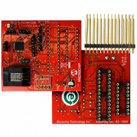
AC162078
Description
HEADER INTRFC MPLAB ICD2 18F1330
Manufacturer
Microchip Technology
Datasheet
1.AC162078.pdf
(318 pages)
Specifications of AC162078
Accessory Type
Transition Header
Lead Free Status / RoHS Status
Not applicable / Not applicable
For Use With/related Products
ICD2
Lead Free Status / RoHS Status
Lead free / RoHS Compliant, Not applicable / Not applicable
Available stocks
Company
Part Number
Manufacturer
Quantity
Price
Company:

Part Number:
AC162078
Manufacturer:
MICROCHIP
Quantity:
12 000


PIC18F1230/1330
14.6.2
The three PWM Duty Cycle registers are double-
buffered to allow glitchless updates of the PWM
outputs. For each duty cycle block, there is a Duty
Cycle Buffer register that is accessible by the user and
a second Duty Cycle register that holds the actual
compare value used in the present PWM period.
In Edge-Aligned PWM Output mode, a new duty cycle
value will be updated whenever a PTMR match with the
PTPER register occurs and PTMR is reset, as shown in
Figure 14-12. Also, the contents of the duty cycle buffers
are automatically loaded into the Duty Cycle registers
when the PWM time base is disabled (PTEN = 0).
When the PWM time base is in the Continuous Up/
Down Count mode, new duty cycle values will be
updated when the value of the PTMR register is zero
and the PWM time base begins to count upwards. The
contents of the duty cycle buffers are automatically
loaded into the Duty Cycle registers when the PWM
time base is disabled (PTEN = 0). Figure 14-13 shows
the timings when the duty cycle update occurs for the
Continuous Up/Down Count mode. In this mode, up to
one entire PWM period is available for calculating and
loading the new PWM duty cycle before changes take
effect.
When the PWM time base is in the Continuous Up/
Down Count mode with double updates, new duty cycle
values will be updated when the value of the PTMR
register is zero and when the value of the PTMR
register matches the value in the PTPER register. The
contents of the duty cycle buffers are automatically
loaded into the Duty Cycle registers during both of the
previously described conditions. Figure 14-14 shows
the duty cycle updates for Continuous Up/Down Count
mode with double updates. In this mode, up to half of a
PWM period is available for calculating and loading the
new PWM duty cycle before changes take effect.
FIGURE 14-13:
DS39758D-page 132
DUTY CYCLE REGISTER BUFFERS
PWM Output
PTMR Value
DUTY CYCLE UPDATE TIMES IN CONTINUOUS UP/DOWN COUNT MODE
Duty Cycle Value Loaded from Buffer Register
14.6.3
Edge-aligned PWM signals are produced by the module
when the PWM time base is in the Free-Running mode
or the Single-Shot mode. For edge-aligned PWM
outputs, the output for a given PWM channel has a
period specified by the value loaded in PTPER and a
duty cycle specified by the appropriate Duty Cycle
register (see Figure 14-12). The PWM output is driven
active at the beginning of the period (PTMR = 0) and is
driven inactive when the value in the Duty Cycle register
matches PTMR. A new cycle is started when PTMR
matches the PTPER, as explained in the PWM period
section.
If the value in a particular Duty Cycle register is zero,
then the output on the corresponding PWM pin will be
inactive for the entire PWM period. In addition, the out-
put on the PWM pin will be active for the entire PWM
period if the value in the Duty Cycle register is greater
than the value held in the PTPER register.
FIGURE 14-12:
Active at
Beginning
of Period
PTPER
New Value Written to Duty Cycle Buffer
PDCx
PDCx
(new)
(old)
0
EDGE-ALIGNED PWM
PTMR
Value
Duty Cycle
Period
EDGE-ALIGNED PWM
2009 Microchip Technology Inc.
New Duty Cycle Latched
Related parts for AC162078
Image
Part Number
Description
Manufacturer
Datasheet
Request
R

Part Number:
Description:
Manufacturer:
Microchip Technology Inc.
Datasheet:
Part Number:
Description:
Manufacturer:
Microchip Technology Inc.
Datasheet:
Part Number:
Description:
Manufacturer:
Microchip Technology Inc.
Datasheet:
Part Number:
Description:
Manufacturer:
Microchip Technology Inc.
Datasheet:
Part Number:
Description:
Manufacturer:
Microchip Technology Inc.
Datasheet:
Part Number:
Description:
Manufacturer:
Microchip Technology Inc.
Datasheet:
Part Number:
Description:
Manufacturer:
Microchip Technology Inc.
Datasheet:
Part Number:
Description:
Manufacturer:
Microchip Technology Inc.
Datasheet: