AC162078 Microchip Technology, AC162078 Datasheet - Page 177
AC162078
Manufacturer Part Number
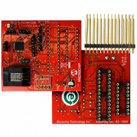
AC162078
Description
HEADER INTRFC MPLAB ICD2 18F1330
Manufacturer
Microchip Technology
Datasheet
1.AC162078.pdf
(318 pages)
Specifications of AC162078
Accessory Type
Transition Header
Lead Free Status / RoHS Status
Not applicable / Not applicable
For Use With/related Products
ICD2
Lead Free Status / RoHS Status
Lead free / RoHS Compliant, Not applicable / Not applicable
Available stocks
Company
Part Number
Manufacturer
Quantity
Price
Company:

Part Number:
AC162078
Manufacturer:
MICROCHIP
Quantity:
12 000


16.7
Figure 16-4 shows the operation of the A/D Converter
after the GO/DONE bit has been set and the
ACQT2:ACQT0 bits are cleared. A conversion is
started after the following instruction to allow entry into
Sleep mode before the conversion begins.
Figure 16-5 shows the operation of the A/D Converter
after the GO/DONE bit has been set, the ACQT2:ACQT0
bits are set to ‘010’ and a 4 T
selected before the conversion starts.
Clearing the GO/DONE bit during a conversion will abort
the current conversion. The A/D Result register pair will
NOT be updated with the partially completed A/D
conversion
ADRESH:ADRESL registers will continue to contain the
value of the last completed conversion (or the last value
written to the ADRESH:ADRESL registers).
FIGURE 16-4:
FIGURE 16-5:
2009 Microchip Technology Inc.
(Holding capacitor continues
acquiring input)
Set GO/DONE bit
1
T
Set GO/DONE bit
CY
A/D Conversions
Holding capacitor is disconnected from analog input (typically 100 ns)
T
ACQT
– T
Acquisition
Automatic
2
AD
Time
sample.
Conversion starts
Cycles
T
AD
3
1 T
A/D CONVERSION T
A/D CONVERSION T
AD
b9
This
4
2 T
Conversion starts
(Holding capacitor is disconnected)
AD
b8
AD
1
means
3 T
acquisition time is
AD
b7
b9
2
4 T
that
AD
b6
On the following cycle:
ADRESH:ADRESL are loaded, GO/DONE bit is cleared,
ADIF bit is set, holding capacitor is connected to analog input.
b8
3
AD
AD
5 T
On the following cycle:
ADRESH:ADRESL are loaded, GO/DONE bit is cleared,
ADIF bit is set, holding capacitor is connected to analog input.
CYCLES (ACQT<2:0> = 000, T
CYCLES (ACQT<2:0> = 010, T
the
AD
b5
b7
4
6 T
AD
b4
T
b6
5
AD
7 T
Cycles
After the A/D conversion is completed or aborted, a
2 T
be started. After this wait, acquisition on the selected
channel is automatically started.
16.8
The discharge phase is used to initialize the value of
the capacitor array. The array is discharged before
every sample. This feature helps to optimize the unity-
gain amplifier, as the circuit always needs to charge the
capacitor array, rather than charge/discharge based on
previous measure values.
AD
b3
Note:
b5
AD
6
8
wait is required before the next acquisition can
T
AD
b2
Discharge
b4
PIC18F1230/1330
7
9 T
The GO/DONE bit should NOT be set in
the same instruction that turns on the A/D.
AD
b1
b3
8
10
T
AD
b0
ACQ
ACQ
b2
9
11
= 0)
T
= 4 T
AD
Discharge
10
b1
1
AD
DS39758D-page 177
b0
)
11
T
Discharge
AD
1
Related parts for AC162078
Image
Part Number
Description
Manufacturer
Datasheet
Request
R

Part Number:
Description:
Manufacturer:
Microchip Technology Inc.
Datasheet:
Part Number:
Description:
Manufacturer:
Microchip Technology Inc.
Datasheet:
Part Number:
Description:
Manufacturer:
Microchip Technology Inc.
Datasheet:
Part Number:
Description:
Manufacturer:
Microchip Technology Inc.
Datasheet:
Part Number:
Description:
Manufacturer:
Microchip Technology Inc.
Datasheet:
Part Number:
Description:
Manufacturer:
Microchip Technology Inc.
Datasheet:
Part Number:
Description:
Manufacturer:
Microchip Technology Inc.
Datasheet:
Part Number:
Description:
Manufacturer:
Microchip Technology Inc.
Datasheet: