KDC5514-Q48EVAL Intersil, KDC5514-Q48EVAL Datasheet - Page 2
KDC5514-Q48EVAL
Manufacturer Part Number
KDC5514-Q48EVAL
Description
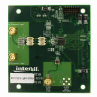
DAUGHTER CARD FOR KAD5514
Manufacturer
Intersil
Series
FemtoCharge™r
Datasheets
1.KAD5514P-25Q72.pdf
(34 pages)
2.KMB-001LEVALZ.pdf
(7 pages)
3.KDC5514EVALZ.pdf
(9 pages)
Specifications of KDC5514-Q48EVAL
Number Of Adc's
1
Number Of Bits
14
Sampling Rate (per Second)
250M
Data Interface
Parallel
Inputs Per Adc
1 Differential
Input Range
1.47 Vpp
Power (typ) @ Conditions
429mW @ 250MSPS
Voltage Supply Source
Single Supply
Operating Temperature
-40°C ~ 85°C
Utilized Ic / Part
KAD5514P-25, KMB001 Motherboard
For Use With
KMB001LEVAL - MOTHERBOARD FOR LVDS ADC CARD
Lead Free Status / RoHS Status
Lead free / RoHS Compliant


Software
The software component is Konverter Analyzer, a
graphical user interface (GUI) created with MATLAB™. A
MATLAB Component Runtime engine is supplied, which
executes a compiled version of the m-files. Therefore a
stand-alone version of MATLAB is not required to run
Konverter Analyzer.
The GUI controls the ADC configuration through the SPI
port, reads data from the motherboard and performs
post-processing and display of the output data. Data can
be viewed in the time or frequency domain, and can be
saved for later processing. Critical performance
parameters such as SNR, SFDR, harmonic distortion, etc.
are calculated and displayed on-screen when viewing in
the frequency domain.
Initial Start-Up
Referring to Figure 1, connect the daughter card to the
motherboard by aligning the two mating mezzanine
connectors. Four screws on the motherboard (not
shown) align with mounting holes in the daughter card.
Next, connect the RF generators to the Clock and Analog
input SMA connectors. Set the clock frequency as desired
with the power level at +10dBm. Similarly, set the
analog input frequency with a power level of
approximately +7dBm (the full-scale value will vary
depending on the loss of the input path and gain of the
ADC). With the RF generators on, apply +5V power
(minimum 5W supply) to the motherboard. The daughter
card is powered by linear regulators on the motherboard.
Daughter Cards
Each daughter card is designed to produce optimal ADC
performance and simplify the evaluation process. Some
boards have multiple connections for the analog input
and clock. For example, low-frequency and
high-frequency input paths are provided on certain
boards. A high-frequency input path may have a balun
interface, while a low frequency path may use a
transformer or buffer amplifier (for DC coupling). Refer to
“Appendix B: Daughter Cards” on page 7 for details on
specific models.
Motherboard
The only connections required for the motherboard are
+5V power and a USB connection to the PC running
Konverter Analyzer. No additional configuration of the
motherboard is required.
Software Start-Up
The FPGA clock is derived from the ADC output clock,
and the FPGA clock must be active for the software to
run properly. Therefore, it’s important that the evaluation
platform is powered and receiving a conversion clock
prior to starting Konverter Analyzer.
2
Application Note 1433
The compressed MATLAB files are unpacked the first time
the GUI is invoked after installation. Subsequently the
graphical window will open more quickly. Complete
information can be found in the KMB-001 Installer
manual.
The main Konverter Analyzer window is shown in
Figure 2. The application opens in FFT mode by default,
but other modes can be selected using the radio buttons
in the lower left corner. In each mode, relevant
parameters are displayed in the data box on the left side
of the window.
The following parameters are displayed in the data box in
all operating modes:
• Fsamp: Sample clock frequency, automatically
• Ffund: Input frequency, automatically detected
• Fund: Input amplitude
• Samples: Record length
• Power: Total power dissipation, as well as the voltage
Data Acquisition
Press the Run button in the lower left corner of the
screen (see Figure 2) to produce a single FFT plot. The
Continuous check box can be selected to capture and
display successive FFT plots. Multiple acquisitions can be
averaged by selecting the Average check box. The
number of averaged acquisitions defaults to 10, but can
be changed in the Setup Conditions dialog.
Menu items and the toolbar buttons may not function
properly if data is being captured in Continuous mode.
Stop the acquisition before selecting a menu item or
using a toolbar button.
detected
(assumes sine wave input)
and current of each supply
FIGURE 2. TIME-DOMAIN DISPLAY
October 1, 2010
AN1433.4
Related parts for KDC5514-Q48EVAL
Image
Part Number
Description
Manufacturer
Datasheet
Request
R

Part Number:
Description:
Intersil Corporation [CMOS Serial Controller Interface]
Manufacturer:
Intersil Corporation
Datasheet:
Part Number:
Description:
Manufacturer:
Intersil Corporation
Datasheet:
Part Number:
Description:
357-036-542-201 CARDEDGE 36POS DL .156 BLK LOPRO
Manufacturer:
Intersil Corporation
Datasheet:
Part Number:
Description:
1024-Word x 4-Bit LSI Static RAM
Manufacturer:
Intersil Corporation
Datasheet:
Part Number:
Description:
General Purpose NPN Transistor Arrays FN341.4
Manufacturer:
Intersil Corporation
Datasheet:
Part Number:
Description:
CMOS 16-Bit Microprocessor
Manufacturer:
Intersil Corporation
Datasheet:
Part Number:
Description:
Manufacturer:
Intersil Corporation
Datasheet:
Part Number:
Description:
Manufacturer:
Intersil Corporation
Datasheet:
Part Number:
Description:
Manufacturer:
Intersil Corporation
Datasheet:
Part Number:
Description:
Manufacturer:
Intersil Corporation
Datasheet:
Part Number:
Description:
CMOS 6-Bit Latch and Decoder Memory Interfaces
Manufacturer:
Intersil Corporation
Datasheet:
Part Number:
Description:
CA3046General Purpose NPN Transistor Arrays
Manufacturer:
Intersil Corporation
Datasheet:
Part Number:
Description:
Manufacturer:
Intersil Corporation
Datasheet:
Part Number:
Description:
TR909 DLC/FLC SLIC with Low Power Standby
Manufacturer:
Intersil Corporation
Datasheet:
Part Number:
Description:
Manufacturer:
Intersil Corporation
Datasheet: