KDC5514-Q48EVAL Intersil, KDC5514-Q48EVAL Datasheet - Page 7
KDC5514-Q48EVAL
Manufacturer Part Number
KDC5514-Q48EVAL
Description
DAUGHTER CARD FOR KAD5514
Manufacturer
Intersil
Series
FemtoCharge™r
Datasheets
1.KAD5514P-25Q72.pdf
(34 pages)
2.KMB-001LEVALZ.pdf
(7 pages)
3.KDC5514EVALZ.pdf
(9 pages)
Specifications of KDC5514-Q48EVAL
Number Of Adc's
1
Number Of Bits
14
Sampling Rate (per Second)
250M
Data Interface
Parallel
Inputs Per Adc
1 Differential
Input Range
1.47 Vpp
Power (typ) @ Conditions
429mW @ 250MSPS
Voltage Supply Source
Single Supply
Operating Temperature
-40°C ~ 85°C
Utilized Ic / Part
KAD5514P-25, KMB001 Motherboard
For Use With
KMB001LEVAL - MOTHERBOARD FOR LVDS ADC CARD
Lead Free Status / RoHS Status
Lead free / RoHS Compliant


The Recalibrate menu item resets the ADC, which forces
a recalibration. The GUI will automatically recalibrate the
ADC when the clock frequency changes if
Setup→AutoRecal is selected.
The Prom Programmer menu item is a password
protected factory function and is not intended for general
usage.
Register Edit allows access to the entire SPI register
map. An example is shown in Figure 12. Refer to the
product datasheet for specific register definitions.
Help
The Diagnostic Dump menu item saves detailed status
information that can be used by the factory to help
troubleshoot operational issues.
About shows version information and can display the
software license agreement.
System Info displays information about the software and
hardware set-up.
Toolbar
Zoom
Selecting one of the magnifying glass icons allows the
axis limits to be changed graphically. Right click in the
graph window for zoom options (horizontal or vertical) or
to reset the axes to default limits.
Pan
The hand icon allows panning the graphic when zoomed.
FIGURE 11. TEMPERATURE SENSOR (VERSION 1.20c
ONLY)
7
Application Note 1433
Markers
Data points can be marked by selecting the marker icon
and clicking on the graphic. Multiple markers can be
placed by selecting Create New Data tip from the
right-click menu. X and Y data is displayed for each
marker.
Appendix A: RF Generators
Intersil uses the following RF generators as clock and
signal sources when characterizing high-speed ADCs:
• Rohde & Schwarz: SMA100A
• Agilent: 8644B (with Low-Noise option)
These generators provide very low jitter to optimize the
SNR performance of the ADC under test. Other
generators with similar phase noise performance can also
be used. Contact Intersil Technical Support for
recommendations.
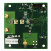
Appendix B: Daughter Cards
KDC5512EVALZ, KDC5512HEVALZ,
KDC5512-50EVALZ, KDC5514EVALZ,
ISLA112P50IR72EV1Z
These daughter cards use a common design to
accommodate the single-input devices from the
KAD55XX and ISLA11XP50 families. They allow for two
clock input paths and two analog input paths. The clock
can be driven through a 4:1 transformer or a CML buffer.
The default clock path is through the Mini-Circuits
TC4-1W transformer (labeled as CLOCK INPUT XFMR on
the PCB). The AC-coupling capacitors in the buffered
path (C46, C47) are not populated. To use the clock
buffer, install 200pF capacitors in positions C46 and C47
and depopulate the AC-coupling capacitors (C28, C29) in
the transformer path.
FIGURE 12. REGISTER EDIT DIALOG
October 1, 2010
AN1433.4
Related parts for KDC5514-Q48EVAL
Image
Part Number
Description
Manufacturer
Datasheet
Request
R

Part Number:
Description:
Intersil Corporation [CMOS Serial Controller Interface]
Manufacturer:
Intersil Corporation
Datasheet:
Part Number:
Description:
Manufacturer:
Intersil Corporation
Datasheet:
Part Number:
Description:
357-036-542-201 CARDEDGE 36POS DL .156 BLK LOPRO
Manufacturer:
Intersil Corporation
Datasheet:
Part Number:
Description:
1024-Word x 4-Bit LSI Static RAM
Manufacturer:
Intersil Corporation
Datasheet:
Part Number:
Description:
General Purpose NPN Transistor Arrays FN341.4
Manufacturer:
Intersil Corporation
Datasheet:
Part Number:
Description:
CMOS 16-Bit Microprocessor
Manufacturer:
Intersil Corporation
Datasheet:
Part Number:
Description:
Manufacturer:
Intersil Corporation
Datasheet:
Part Number:
Description:
Manufacturer:
Intersil Corporation
Datasheet:
Part Number:
Description:
Manufacturer:
Intersil Corporation
Datasheet:
Part Number:
Description:
Manufacturer:
Intersil Corporation
Datasheet:
Part Number:
Description:
CMOS 6-Bit Latch and Decoder Memory Interfaces
Manufacturer:
Intersil Corporation
Datasheet:
Part Number:
Description:
CA3046General Purpose NPN Transistor Arrays
Manufacturer:
Intersil Corporation
Datasheet:
Part Number:
Description:
Manufacturer:
Intersil Corporation
Datasheet:
Part Number:
Description:
TR909 DLC/FLC SLIC with Low Power Standby
Manufacturer:
Intersil Corporation
Datasheet:
Part Number:
Description:
Manufacturer:
Intersil Corporation
Datasheet: