KDC5514-Q48EVAL Intersil, KDC5514-Q48EVAL Datasheet - Page 6
KDC5514-Q48EVAL
Manufacturer Part Number
KDC5514-Q48EVAL
Description
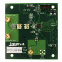
DAUGHTER CARD FOR KAD5514
Manufacturer
Intersil
Series
FemtoCharge™r
Datasheets
1.KAD5514P-25Q72.pdf
(34 pages)
2.KMB-001LEVALZ.pdf
(7 pages)
3.KDC5514EVALZ.pdf
(9 pages)
Specifications of KDC5514-Q48EVAL
Number Of Adc's
1
Number Of Bits
14
Sampling Rate (per Second)
250M
Data Interface
Parallel
Inputs Per Adc
1 Differential
Input Range
1.47 Vpp
Power (typ) @ Conditions
429mW @ 250MSPS
Voltage Supply Source
Single Supply
Operating Temperature
-40°C ~ 85°C
Utilized Ic / Part
KAD5514P-25, KMB001 Motherboard
For Use With
KMB001LEVAL - MOTHERBOARD FOR LVDS ADC CARD
Lead Free Status / RoHS Status
Lead free / RoHS Compliant


The Register Control Panel (Figure 9) is used to adjust
the gain, offset and clock skew of the ADC cores and
control various functional settings such as data format
and output mode. The Phase setting is differential in
nature and therefore is only applicable for products with
two ADC cores (e.g. KAD5512P-50 and KAD56XX).
Gain and Offset adjustments are made to each ADC core
individually. The Channel A/Channel B button selects
which core is adjusted. Gain can be adjusted in coarse,
medium and fine steps, while offset is adjusted in coarse
and fine steps (refer to the product datasheet for the
adjustment range and resolution).
Values can be entered manually or adjusted with the
slider controls. The Read All button reads the value for
each ADC register and adjusts the slider display if
necessary. Write All commits the entered values to the
ADC. It’s not necessary to use Write All when using the
sliders—any changes made are committed immediately.
The ‘Automatic Interleave Calibration’ button executes an
algorithm which attempts to match the gain, offset and
timing skew between unit ADCs (applies to interleaved
FIGURE 9. REGISTER CONTROL PANEL
6
Application Note 1433
ADCs only). After execution, the fundamental image spur
(FIS) and offset spur (OS) should both be minimized.
This command can be executed after the sample rate or
input frequency change substantially.
Operation of the I2E engine is controlled in the Interleave
Control Panel (version 1.20c only, Figure 10). The OGP
On/Off button determines if updates are made to the unit
ADCs, while the bars to the right show the current state
of the Offset, Gain and Delay adjustments.
FIGURE 10. INTERLEAVE CONTROL PANEL (VERSION
In the Configuration section, each adjustment (Offset,
Gain and Delay) can be individually enabled and
controlled. The number of Samples per Iteration
determines how quickly the algorithm will converge,
while the Final Step Size sets the granularity.
Randomization of the iteration length is recommended
for optimum performance, but this can be disabled.
The Power Meter sets the minimum power threshold that
the input signal must cross for the algorithm to apply
correction factors.
Refer to the applicable product datasheet for more detail
on the functions and control of the I2E algorithm.
Some products have an internal temperature sensor,
which is accessed using the Temperature Sensor window
(version 1.20c only, Figure 11). The absolute accuracy of
the internal temperature monitor can range from ±10%
to ±15%, but relative accuracy (i.e. accuracy of
detecting temperature changes) is much better. The
temperature display assumes that the ADC is operating
at room temperature (+25°C) when the GUI is invoked.
1.20c ONLY)
October 1, 2010
AN1433.4
Related parts for KDC5514-Q48EVAL
Image
Part Number
Description
Manufacturer
Datasheet
Request
R

Part Number:
Description:
Intersil Corporation [CMOS Serial Controller Interface]
Manufacturer:
Intersil Corporation
Datasheet:
Part Number:
Description:
Manufacturer:
Intersil Corporation
Datasheet:
Part Number:
Description:
357-036-542-201 CARDEDGE 36POS DL .156 BLK LOPRO
Manufacturer:
Intersil Corporation
Datasheet:
Part Number:
Description:
1024-Word x 4-Bit LSI Static RAM
Manufacturer:
Intersil Corporation
Datasheet:
Part Number:
Description:
General Purpose NPN Transistor Arrays FN341.4
Manufacturer:
Intersil Corporation
Datasheet:
Part Number:
Description:
CMOS 16-Bit Microprocessor
Manufacturer:
Intersil Corporation
Datasheet:
Part Number:
Description:
Manufacturer:
Intersil Corporation
Datasheet:
Part Number:
Description:
Manufacturer:
Intersil Corporation
Datasheet:
Part Number:
Description:
Manufacturer:
Intersil Corporation
Datasheet:
Part Number:
Description:
Manufacturer:
Intersil Corporation
Datasheet:
Part Number:
Description:
CMOS 6-Bit Latch and Decoder Memory Interfaces
Manufacturer:
Intersil Corporation
Datasheet:
Part Number:
Description:
CA3046General Purpose NPN Transistor Arrays
Manufacturer:
Intersil Corporation
Datasheet:
Part Number:
Description:
Manufacturer:
Intersil Corporation
Datasheet:
Part Number:
Description:
TR909 DLC/FLC SLIC with Low Power Standby
Manufacturer:
Intersil Corporation
Datasheet:
Part Number:
Description:
Manufacturer:
Intersil Corporation
Datasheet: