KDC5514-Q48EVAL Intersil, KDC5514-Q48EVAL Datasheet - Page 3
KDC5514-Q48EVAL
Manufacturer Part Number
KDC5514-Q48EVAL
Description
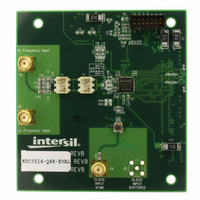
DAUGHTER CARD FOR KAD5514
Manufacturer
Intersil
Series
FemtoCharge™r
Datasheets
1.KAD5514P-25Q72.pdf
(34 pages)
2.KMB-001LEVALZ.pdf
(7 pages)
3.KDC5514EVALZ.pdf
(9 pages)
Specifications of KDC5514-Q48EVAL
Number Of Adc's
1
Number Of Bits
14
Sampling Rate (per Second)
250M
Data Interface
Parallel
Inputs Per Adc
1 Differential
Input Range
1.47 Vpp
Power (typ) @ Conditions
429mW @ 250MSPS
Voltage Supply Source
Single Supply
Operating Temperature
-40°C ~ 85°C
Utilized Ic / Part
KAD5514P-25, KMB001 Motherboard
For Use With
KMB001LEVAL - MOTHERBOARD FOR LVDS ADC CARD
Lead Free Status / RoHS Status
Lead free / RoHS Compliant


Display Options
Time-Domain Display
The time-domain display mode shows ADC code versus
sample number for the complete data record (Figure 2).
In addition to the standard parameters, the following are
displayed:
• Min: Minimum code in data record
• Max: Maximum code in data record
• Range: Code Range (Max – Min)
• Mean: Mean of data record
• FS: Full-scale code
FIGURE 3. FREQUENCY-DOMAIN DISPLAY
FIGURE 4. LOGIC DISPLAY
3
Application Note 1433
Frequency-Domain Display
The Fast Fourier Transform (FFT) of the data record is
displayed from DC to the Nyquist frequency (f
shown in Figure 3. The following unique parameters are
displayed in this mode:
• SNRFS: Signal-to-Noise Ratio related to the ADC
• SNR: Signal-to-Noise Ratio related to the input
• SFDR: Spurious-Free Dynamic Range
• SINAD: Signal-to-Noise And Distortion ratio
• THD: Total Harmonic Distortion
• HD2—HD7: Second Harmonic Distortion Component
• FIS: Fundamental Image Spur (interleaved mode
• OS: Offset Spur (interleaved mode only)
• ENOB: Effective Number Of Bits
• ENOBFS: ENOB – (Fundamental Amplitude)/6.02
• Window: Window type. Options are Hanning,
The location of harmonics HD2 through HD10 are
indicated with red numbers on the FFT display. The
largest frequency spur, which determines the SFDR
value, is marked with a red ‘+’ symbol.
For interleaved ADCs there are two additional marked
spurs: the Fundamental Image Spur (FIS) and the Offset
Spur (OS). These spurs arise in interleaved ADCs due to
imperfect matching between the unit ADCs. The FIS
occurs at the unit ADC sample rate minus the input
frequency, while the OS occurs at the unit ADC sample
rate.
When the ISLA112P50 daughter card is connected, the
Background Interleave Cal button is enabled. This allows
the user to turn the Intersil Interleave Engine (I2E) on or
off. Full control of the I2E block is accomplished using the
Interleave Control Panel.
Logic Display
The logic value for each output bit is displayed versus
sample number for the complete data record, similar to a
logic analyzer (Figure 4). The displayed parameters are
the same as those in Time mode.
Logic mode may operate very slowly with large data
records. If a warning dialog is displayed when switching
to Logic mode, reduce the record length using the Setup
FFT dialog.
Full-Scale input
signal power
(HD2) through seventh Harmonic Distortion
Component (HD7)
only)
Blackman-Harris 4-Term or None.
October 1, 2010
S
/2), as
AN1433.4
Related parts for KDC5514-Q48EVAL
Image
Part Number
Description
Manufacturer
Datasheet
Request
R

Part Number:
Description:
Intersil Corporation [CMOS Serial Controller Interface]
Manufacturer:
Intersil Corporation
Datasheet:
Part Number:
Description:
Manufacturer:
Intersil Corporation
Datasheet:
Part Number:
Description:
357-036-542-201 CARDEDGE 36POS DL .156 BLK LOPRO
Manufacturer:
Intersil Corporation
Datasheet:
Part Number:
Description:
1024-Word x 4-Bit LSI Static RAM
Manufacturer:
Intersil Corporation
Datasheet:
Part Number:
Description:
General Purpose NPN Transistor Arrays FN341.4
Manufacturer:
Intersil Corporation
Datasheet:
Part Number:
Description:
CMOS 16-Bit Microprocessor
Manufacturer:
Intersil Corporation
Datasheet:
Part Number:
Description:
Manufacturer:
Intersil Corporation
Datasheet:
Part Number:
Description:
Manufacturer:
Intersil Corporation
Datasheet:
Part Number:
Description:
Manufacturer:
Intersil Corporation
Datasheet:
Part Number:
Description:
Manufacturer:
Intersil Corporation
Datasheet:
Part Number:
Description:
CMOS 6-Bit Latch and Decoder Memory Interfaces
Manufacturer:
Intersil Corporation
Datasheet:
Part Number:
Description:
CA3046General Purpose NPN Transistor Arrays
Manufacturer:
Intersil Corporation
Datasheet:
Part Number:
Description:
Manufacturer:
Intersil Corporation
Datasheet:
Part Number:
Description:
TR909 DLC/FLC SLIC with Low Power Standby
Manufacturer:
Intersil Corporation
Datasheet:
Part Number:
Description:
Manufacturer:
Intersil Corporation
Datasheet: