ATEVK1104 Atmel, ATEVK1104 Datasheet - Page 83
ATEVK1104
Manufacturer Part Number
ATEVK1104
Description
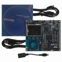
KIT DEV/EVAL FOR AVR32 AT32UC3A
Manufacturer
Atmel
Series
AVR®32r
Type
MCUr
Datasheets
1.ATAVRONE-PROBECBL.pdf
(16 pages)
2.ATEVK1104.pdf
(826 pages)
3.ATEVK1104.pdf
(90 pages)
4.ATEVK1104.pdf
(6 pages)
5.ATEVK1104.pdf
(12 pages)
Specifications of ATEVK1104
Contents
Evaluation Board, Software and Documentation
Processor To Be Evaluated
AT32UC3A3
Data Bus Width
32 bit
Interface Type
USB, SPI, USART
Silicon Manufacturer
Atmel
Core Architecture
AVR
Core Sub-architecture
AVR UC3
Silicon Core Number
AT32UC3A3256
Silicon Family Name
AVR
Kit Contents
Board CD Docs
Rohs Compliant
Yes
For Use With/related Products
AT32UC3A3
Lead Free Status / RoHS Status
Lead free / RoHS Compliant
Available stocks
Company
Part Number
Manufacturer
Quantity
Price
Company:

Part Number:
ATEVK1104
Manufacturer:
Atmel
Quantity:
135


13.2.5
13.2.6
32072C–AVR32–2010/03
SPI
USART
1. SPI Bad Serial Clock Generation on 2nd chip_select when SCBR = 1, CPOL=1 and
2. SPI Disable does not work in Slave mode
3. SPI RDR.PCS is not correct
4. SPI data transfer hangs with CSAAT=1 in CSR0 and MODFDIS=0 in MR
5. Disabling SPI has no effect on the TDRE flag
1. The NER register always returns zero.
2. USART - RTS output signal does not function properly in hardware handshaking
Activate the sleep mode in the mode register and then perform an AD conversion.
NCPHA=0
When multiple CS are in use, if one of the baudrate equals to 1 and one of the others doesn't
equal to 1, and CPOL=1 and CPHA=0, then an additional pulse will be generated on SCK.
Fix/workaround
When multiple CS are in use, if one of the baudrate equals 1, the other must
also equal 1 if CPOL=1 and CPHA=0.
Fix/workaround
Read the last received data then perform a Software reset.
The PCS (Peripheral Chip Select) field in the SPI RDR (Receive Data Register) does not
correctly indicate the value on the NPCS pins at the end of a transfer.
Fix/Workaround
Do not use the PCS field of the SPI RDR.
When CSAAT=1 in CSR0 and mode fault detection is enabled (MODFDIS=0 in MR), the
SPI module will not start a data transfer.
Fix/Workaround
Disable mode fault detection by writing a one to MODFDIS in MR.
Disabling SPI has no effect on TDRE whereas the write data command is filtered when SPI
is disabled. This means that as soon as the SPI is disabled it becomes impossible to reset
the TDRE flag by writing in the TDR. So if the SPI is disabled during a PDCA transfer, the
PDCA will continue to write data in the TDR (as TDRE stays high) until its buffer is empty,
and all data written after the disable command is lost.
Fix/Workaround
Disable the PDCA, 2 NOP (minimum), disable SPI. When you want to continue the transfer:
Enable SPI, enable PDCA.
Fix/Workaround
None.
mode
The RTS signal is not generated properly when the USART receives data in hardware hand-
shaking mode. When the Peripheral DMA receive buffer becomes full, the RTS output
should go high, but it will stay low.
Fix/Workaround
Do not use the hardware handshaking mode of the USART. If it is necessary to drive the
RTS output high when the Peripheral DMA receive buffer becomes full, use the normal
mode of the USART. Configure the Peripheral DMA Controller to signal an interrupt when
the receive buffer is full. In the interrupt handler code, write a one to the RTSDIS bit in the
AT32UC3A3/A4
83
Related parts for ATEVK1104
Image
Part Number
Description
Manufacturer
Datasheet
Request
R

Part Number:
Description:
DEV KIT FOR AVR/AVR32
Manufacturer:
Atmel
Datasheet:

Part Number:
Description:
INTERVAL AND WIPE/WASH WIPER CONTROL IC WITH DELAY
Manufacturer:
ATMEL Corporation
Datasheet:
Part Number:
Description:
Low-Voltage Voice-Switched IC for Hands-Free Operation
Manufacturer:
ATMEL Corporation
Datasheet:
Part Number:
Description:
MONOLITHIC INTEGRATED FEATUREPHONE CIRCUIT
Manufacturer:
ATMEL Corporation
Datasheet:
Part Number:
Description:
AM-FM Receiver IC U4255BM-M
Manufacturer:
ATMEL Corporation
Datasheet:
Part Number:
Description:
Monolithic Integrated Feature Phone Circuit
Manufacturer:
ATMEL Corporation
Datasheet:
Part Number:
Description:
Multistandard Video-IF and Quasi Parallel Sound Processing
Manufacturer:
ATMEL Corporation
Datasheet:
Part Number:
Description:
High-performance EE PLD
Manufacturer:
ATMEL Corporation
Datasheet:
Part Number:
Description:
8-bit Flash Microcontroller
Manufacturer:
ATMEL Corporation
Datasheet:
Part Number:
Description:
2-Wire Serial EEPROM
Manufacturer:
ATMEL Corporation
Datasheet: