AT91SAM9M10-G45-EK Atmel, AT91SAM9M10-G45-EK Datasheet - Page 344
AT91SAM9M10-G45-EK
Manufacturer Part Number
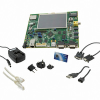
AT91SAM9M10-G45-EK
Description
KIT EVAL FOR AT91SAMG45/9M10
Manufacturer
Atmel
Series
AT91SAM Smart ARMr
Type
MCUr
Specifications of AT91SAM9M10-G45-EK
Contents
Board, Cables, Power Supply
Processor To Be Evaluated
AT91SAM9M10
Processor Series
AT91SAM9
Data Bus Width
32 bit
Interface Type
RS-232, Ethernet, USB, JTAG
Operating Supply Voltage
5 V
Silicon Manufacturer
Atmel
Core Architecture
AVR
Kit Contents
Board
Features
Two High Speed USB Hosts, LCD TFT Display
Svhc
No SVHC (15-Dec-2010)
Mcu Supported Families
AT91SAM9M10,
Rohs Compliant
Yes
For Use With/related Products
AT91SAM9M10
Lead Free Status / RoHS Status
Lead free / RoHS Compliant
Available stocks
Company
Part Number
Manufacturer
Quantity
Price
Company:

Part Number:
AT91SAM9M10-G45-EK
Manufacturer:
INFINEON
Quantity:
10 000
Company:
Part Number:
AT91SAM9M10-G45-EK
Manufacturer:
Atmel
Quantity:
135


26.2.1.3
26.3
26.4
344
Master Clock Controller
Processor Clock Controller
AT91SAM9M10
No UDP HS, UHP FS and DDR2 Mode
The Master Clock Controller provides selection and division of the Master Clock (MCK). MCK is
the clock provided to all the peripherals and the memory controller.
The Master Clock is selected from one of the clocks provided by the Clock Generator. Selecting
the Slow Clock provides a Slow Clock signal to the whole device. Selecting the Main Clock
saves power consumption of the PLLA.
The Master Clock Controller is made up of a clock selector and a prescaler. It also contains a
Master Clock divider which allows the processor clock to be faster than the Master Clock.
The Master Clock selection is made by writing the CSS field (Clock Source Selection) in
PMC_MCKR (Master Clock Register). The prescaler supports the division by a power of 2 of the
selected clock between 1 and 64. The PRES field in PMC_MCKR programs the prescaler. The
Master Clock divider can be programmed through the MDIV field in PMC_MCKR.
Note:
Each time PMC_MCKR is written to define a new Master Clock, the MCKRDY bit is cleared in
PMC_SR. It reads 0 until the Master Clock is established. Then, the MCKRDY bit is set and can
trigger an interrupt to the processor. This feature is useful when switching from a high-speed
clock to a lower one to inform the software when the change is actually done.
Figure 26-2. Master Clock Controller
The PMC features a Processor Clock Controller (PCK) that implements the Processor Idle
Mode. The Processor Clock can be disabled by writing the System Clock Disable Register
• Only PLLA is running at 384 MHz, UPLL power consumption is saved
• USB Device High Speed and Host EHCI High Speed operations are NOT allowed
• Full Speed OHCI input clock is PLLACK, USBDIV is 7 (division by 8)
• System Input clock is PLLACK, PCK is 384 MHz
• MDIV is ‘11’, MCK is 128 MHz
• DDR2 can be used at up to 128 MHz
MAINCK
UPLLCK
PLLACK
SLCK
It is forbidden to modify MDIV and CSS at the same access. Each field must be modified sepa-
rately with a wait for MCKRDY flag between the first field modification and the second field
modification.
PMC_MCKR
CSS
Master Clock
PMC_MCKR
Prescaler
PRES
PMC_MCKR
Processor
Master
Divider
Divider
Clock
Clock
MDIV
MCK
To the Processor
Clock Controller (PCK)
6355B–ATARM–21-Jun-10
Related parts for AT91SAM9M10-G45-EK
Image
Part Number
Description
Manufacturer
Datasheet
Request
R

Part Number:
Description:
KIT EVAL FOR AT91SAM9M10
Manufacturer:
Atmel
Datasheet:

Part Number:
Description:
IC MCU 16/32BIT ARM9 324TFBGA
Manufacturer:
Atmel
Datasheet:

Part Number:
Description:
At91 Arm Thumb-based Microcontrollers
Manufacturer:
ATMEL Corporation
Datasheet:

Part Number:
Description:
MCU, MPU & DSP Development Tools KICKSTART KIT FOR AT91SAM9 PLUS
Manufacturer:
IAR Systems

Part Number:
Description:
DEV KIT FOR AVR/AVR32
Manufacturer:
Atmel
Datasheet:
Part Number:
Description:
INTERVAL AND WIPE/WASH WIPER CONTROL IC WITH DELAY
Manufacturer:
ATMEL Corporation
Datasheet:
Part Number:
Description:
Low-Voltage Voice-Switched IC for Hands-Free Operation
Manufacturer:
ATMEL Corporation
Datasheet:
Part Number:
Description:
MONOLITHIC INTEGRATED FEATUREPHONE CIRCUIT
Manufacturer:
ATMEL Corporation
Datasheet:
Part Number:
Description:
AM-FM Receiver IC U4255BM-M
Manufacturer:
ATMEL Corporation
Datasheet:
Part Number:
Description:
Monolithic Integrated Feature Phone Circuit
Manufacturer:
ATMEL Corporation
Datasheet:
Part Number:
Description:
Multistandard Video-IF and Quasi Parallel Sound Processing
Manufacturer:
ATMEL Corporation
Datasheet:
Part Number:
Description:
High-performance EE PLD
Manufacturer:
ATMEL Corporation
Datasheet: