AT91SAM9M10-G45-EK Atmel, AT91SAM9M10-G45-EK Datasheet - Page 935
AT91SAM9M10-G45-EK
Manufacturer Part Number
AT91SAM9M10-G45-EK
Description
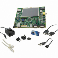
KIT EVAL FOR AT91SAMG45/9M10
Manufacturer
Atmel
Series
AT91SAM Smart ARMr
Type
MCUr
Specifications of AT91SAM9M10-G45-EK
Contents
Board, Cables, Power Supply
Processor To Be Evaluated
AT91SAM9M10
Processor Series
AT91SAM9
Data Bus Width
32 bit
Interface Type
RS-232, Ethernet, USB, JTAG
Operating Supply Voltage
5 V
Silicon Manufacturer
Atmel
Core Architecture
AVR
Kit Contents
Board
Features
Two High Speed USB Hosts, LCD TFT Display
Svhc
No SVHC (15-Dec-2010)
Mcu Supported Families
AT91SAM9M10,
Rohs Compliant
Yes
For Use With/related Products
AT91SAM9M10
Lead Free Status / RoHS Status
Lead free / RoHS Compliant
Available stocks
Company
Part Number
Manufacturer
Quantity
Price
Company:

Part Number:
AT91SAM9M10-G45-EK
Manufacturer:
INFINEON
Quantity:
10 000
Company:
Part Number:
AT91SAM9M10-G45-EK
Manufacturer:
Atmel
Quantity:
135


40.6.4
40.6.5
40.7
40.7.1
6355B–ATARM–21-Jun-10
Touch Screen
Startup Time
Sample and Hold Time
Resistive Touch Screen Principles
The Touch Screen ADC has a minimal Startup Time when it exits the Sleep Mode. As the ADC
Clock depends on the application, the user has to program the field STARTUP in the
Mode
conversion of the sequence.
The field STARTUP can define a Startup Time between 8 and 1024 ADC Clock cycles by steps
of 8.
The user must assure that ADC Startup Time given in the section “Electrical Characteristics” is
covered by this wait time.
In the same way, a minimal Sample and Hold Time is necessary for the TSADCC to guarantee
the best converted final value between selection of two channels. This time depends on the input
impedance of the analog input, but also on the output impedance of the driver providing the sig-
nal to the analog input, as there is no input buffer amplifier.
The Sample and Hold time has to be programmed through the bitfields SHTIM in the
Mode Register”
The field SHTIM defines the number of ADC Clock cycles for an analog input, while the field
TSSHTIM defines the number of ADC Clock cycles for a Touch Screen input.
These both fields can define a Sample and Hold time between 1 and 16 ADC Clock cycles.
The field TSSHTIM defines also the time the power switches of the Touch Screen are closed
when the TSADCC performs a conversion for the Touch Screen.
A resistive touch screen is based on two resistive films, each one being fitted with a pair of elec-
trodes, placed at the top and bottom on one film, and on the right and left on the other. Between
the two, there is a layer that acts as an insulator, but also enables contact when you press the
screen. This is illustrated in
The TSADC controller has the ability to perform without external components:
• Position Measurement
• Pressure Measurement
• Pen Detection
Register”, which defines how many ADC Clock cycles to wait before performing the first
and TSSHTIM in the
Figure
40-2.
“TSADCC Touch Screen
Register”.
AT91SAM9M10
“TSADCC
“TSADCC
935
Related parts for AT91SAM9M10-G45-EK
Image
Part Number
Description
Manufacturer
Datasheet
Request
R

Part Number:
Description:
KIT EVAL FOR AT91SAM9M10
Manufacturer:
Atmel
Datasheet:

Part Number:
Description:
IC MCU 16/32BIT ARM9 324TFBGA
Manufacturer:
Atmel
Datasheet:

Part Number:
Description:
At91 Arm Thumb-based Microcontrollers
Manufacturer:
ATMEL Corporation
Datasheet:

Part Number:
Description:
MCU, MPU & DSP Development Tools KICKSTART KIT FOR AT91SAM9 PLUS
Manufacturer:
IAR Systems

Part Number:
Description:
DEV KIT FOR AVR/AVR32
Manufacturer:
Atmel
Datasheet:
Part Number:
Description:
INTERVAL AND WIPE/WASH WIPER CONTROL IC WITH DELAY
Manufacturer:
ATMEL Corporation
Datasheet:
Part Number:
Description:
Low-Voltage Voice-Switched IC for Hands-Free Operation
Manufacturer:
ATMEL Corporation
Datasheet:
Part Number:
Description:
MONOLITHIC INTEGRATED FEATUREPHONE CIRCUIT
Manufacturer:
ATMEL Corporation
Datasheet:
Part Number:
Description:
AM-FM Receiver IC U4255BM-M
Manufacturer:
ATMEL Corporation
Datasheet:
Part Number:
Description:
Monolithic Integrated Feature Phone Circuit
Manufacturer:
ATMEL Corporation
Datasheet:
Part Number:
Description:
Multistandard Video-IF and Quasi Parallel Sound Processing
Manufacturer:
ATMEL Corporation
Datasheet:
Part Number:
Description:
High-performance EE PLD
Manufacturer:
ATMEL Corporation
Datasheet: