AT91SAM9M10-G45-EK Atmel, AT91SAM9M10-G45-EK Datasheet - Page 59
AT91SAM9M10-G45-EK
Manufacturer Part Number
AT91SAM9M10-G45-EK
Description
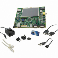
KIT EVAL FOR AT91SAMG45/9M10
Manufacturer
Atmel
Series
AT91SAM Smart ARMr
Type
MCUr
Specifications of AT91SAM9M10-G45-EK
Contents
Board, Cables, Power Supply
Processor To Be Evaluated
AT91SAM9M10
Processor Series
AT91SAM9
Data Bus Width
32 bit
Interface Type
RS-232, Ethernet, USB, JTAG
Operating Supply Voltage
5 V
Silicon Manufacturer
Atmel
Core Architecture
AVR
Kit Contents
Board
Features
Two High Speed USB Hosts, LCD TFT Display
Svhc
No SVHC (15-Dec-2010)
Mcu Supported Families
AT91SAM9M10,
Rohs Compliant
Yes
For Use With/related Products
AT91SAM9M10
Lead Free Status / RoHS Status
Lead free / RoHS Compliant
Available stocks
Company
Part Number
Manufacturer
Quantity
Price
Company:

Part Number:
AT91SAM9M10-G45-EK
Manufacturer:
INFINEON
Quantity:
10 000
Company:
Part Number:
AT91SAM9M10-G45-EK
Manufacturer:
Atmel
Quantity:
135


11.3
11.3.1
11.3.2
6355B–ATARM–21-Jun-10
Device Initialization
Clock at Start Up
Initialization Sequence
At boot start up, the processor clock (PCK) and the master clock (MCK) are found on the slow
clock. The slow clock can be an external 32 kHz crystal oscillator or the internal RC oscillator. By
default the slow clock is the internal RC oscillator. Its frequency is not precise and is between 20
kHz and 40 kHz. Its start up is much faster than an external 32 kHz quartz. If a battery supplies
the backup power and if the external 32 kHz clock was previously started up and selected, the
slow clock at boot is the external 32 kHz quartz oscillator. Refer to the Slow Clock Crystal Oscil-
lator description in the Clock Generator section of the datasheet.
Initialization follows the steps described below:
1. Stack setup for ARM supervisor mode.
2. Main Oscillator Detection: (External crystal or external clock on XIN). The Main Oscil-
3. Main Oscillator Enabling: if an external clock is connected on XIN, the Main Oscillator
4. Main Oscillator Selection: the Master Clock source is switched from Slow Clock to the
5. C variable initialization: non zero-initialized data are initialized in RAM (copy from
6. PLLA initialization: PLLA is configured to allow communication on the USB link for the
lator is disabled at startup (MOSCEN = 0). First it is bypassed (OSCBYPASS set at 1).
Then the MAINRDY bit is polled. Since this bit is raised, the Main Clock Frequency field
is analyzed (MAINF). If the value is bigger than 16, an external clock connected on XIN
is detected. If not, an external quartz connected between XIN and XOUT (whose fre-
quency is unknown at this moment) is detected.
does not need to be started. Otherwise, the OSCBYPASS bit is not set. The Main Oscil-
lator is enabled (MOSCEN = 1) with the maximum start-up time and the MOSC bit is
polled to wait for stabilization.
Main Oscillator without prescaler. The PMC Status Register is polled to wait for MCK
Ready. PCK and MCK are now the Main Oscillator clock.
ROM to RAM). Zero-initialized data are set to 0 in RAM.
SAM-BA Monitor. Its configuration depends on the Main Oscillator source (external
clock or crystal) and on its frequency.
AT91SAM9M10
59
Related parts for AT91SAM9M10-G45-EK
Image
Part Number
Description
Manufacturer
Datasheet
Request
R

Part Number:
Description:
KIT EVAL FOR AT91SAM9M10
Manufacturer:
Atmel
Datasheet:

Part Number:
Description:
IC MCU 16/32BIT ARM9 324TFBGA
Manufacturer:
Atmel
Datasheet:

Part Number:
Description:
At91 Arm Thumb-based Microcontrollers
Manufacturer:
ATMEL Corporation
Datasheet:

Part Number:
Description:
MCU, MPU & DSP Development Tools KICKSTART KIT FOR AT91SAM9 PLUS
Manufacturer:
IAR Systems

Part Number:
Description:
DEV KIT FOR AVR/AVR32
Manufacturer:
Atmel
Datasheet:
Part Number:
Description:
INTERVAL AND WIPE/WASH WIPER CONTROL IC WITH DELAY
Manufacturer:
ATMEL Corporation
Datasheet:
Part Number:
Description:
Low-Voltage Voice-Switched IC for Hands-Free Operation
Manufacturer:
ATMEL Corporation
Datasheet:
Part Number:
Description:
MONOLITHIC INTEGRATED FEATUREPHONE CIRCUIT
Manufacturer:
ATMEL Corporation
Datasheet:
Part Number:
Description:
AM-FM Receiver IC U4255BM-M
Manufacturer:
ATMEL Corporation
Datasheet:
Part Number:
Description:
Monolithic Integrated Feature Phone Circuit
Manufacturer:
ATMEL Corporation
Datasheet:
Part Number:
Description:
Multistandard Video-IF and Quasi Parallel Sound Processing
Manufacturer:
ATMEL Corporation
Datasheet:
Part Number:
Description:
High-performance EE PLD
Manufacturer:
ATMEL Corporation
Datasheet: