AT91SAM9G10-EK Atmel, AT91SAM9G10-EK Datasheet - Page 436
AT91SAM9G10-EK
Manufacturer Part Number
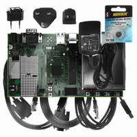
AT91SAM9G10-EK
Description
KIT DEV FOR SAM9G10 ARM
Manufacturer
Atmel
Type
MCUr
Specifications of AT91SAM9G10-EK
Contents
Board, Cables, Power Supply
Silicon Manufacturer
Atmel
Core Architecture
AVR
Kit Contents
Board
Svhc
No SVHC (15-Dec-2010)
Mcu Supported Families
AT91SAM9G10, ARM926EJ-S
Tool / Board Applications
Microcontroller
Rohs Compliant
Yes
For Use With/related Products
*
Lead Free Status / RoHS Status
Contains lead / RoHS non-compliant


Figure 32-18. ASK Modulator Output
Figure 32-19. FSK Modulator Output
32.6.3.7
Figure 32-20. Synchronous Mode Character Reception
6462A–ATARM–03-Jun-09
Uptstream Frequency F0
Uptstream Frequencies
unipolar output
FSK Modulator
ASK Modulator
default polarity
[F0, F0+offset]
unipolar output
default polarity
NRZ stream
NRZ stream
Manchester
Manchester
Synchronous Receiver
encoded
encoded
Output
Output
data
data
Example: 8-bit, Parity Enabled 1 Stop
Baud Rate
Sampling
Clock
RXD
Txd
Txd
1
1
switches to receiving mode. The demodulated stream is sent to the Manchester decoder.
Because of bit checking inside RF IC, the data transferred to the microcontroller is reduced by a
user-defined number of bits. The Manchester preamble length is to be defined in accordance
with the RF IC configuration.
In synchronous mode (SYNC = 1), the receiver samples the RXD signal on each rising edge of
the Baud Rate Clock. If a low level is detected, it is considered as a start. All data bits, the parity
bit and the stop bits are sampled and the receiver waits for the next start bit. Synchronous mode
operations provide a high speed transfer capability.
Configuration fields and bits are the same as in asynchronous mode.
Figure 32-20
Start
illustrates a character reception in synchronous mode.
D0
D1
0
0
D2
D3
D4
0
0
D5
D6
D7
Parity Bit
AT91SAM9G10
Stop Bit
1
1
436
Related parts for AT91SAM9G10-EK
Image
Part Number
Description
Manufacturer
Datasheet
Request
R

Part Number:
Description:
MCU, MPU & DSP Development Tools KICKSTART KIT FOR AT91SAM9 PLUS
Manufacturer:
IAR Systems

Part Number:
Description:
DEV KIT FOR AVR/AVR32
Manufacturer:
Atmel
Datasheet:

Part Number:
Description:
INTERVAL AND WIPE/WASH WIPER CONTROL IC WITH DELAY
Manufacturer:
ATMEL Corporation
Datasheet:
Part Number:
Description:
Low-Voltage Voice-Switched IC for Hands-Free Operation
Manufacturer:
ATMEL Corporation
Datasheet:
Part Number:
Description:
MONOLITHIC INTEGRATED FEATUREPHONE CIRCUIT
Manufacturer:
ATMEL Corporation
Datasheet:
Part Number:
Description:
AM-FM Receiver IC U4255BM-M
Manufacturer:
ATMEL Corporation
Datasheet:
Part Number:
Description:
Monolithic Integrated Feature Phone Circuit
Manufacturer:
ATMEL Corporation
Datasheet:
Part Number:
Description:
Multistandard Video-IF and Quasi Parallel Sound Processing
Manufacturer:
ATMEL Corporation
Datasheet:
Part Number:
Description:
High-performance EE PLD
Manufacturer:
ATMEL Corporation
Datasheet:
Part Number:
Description:
8-bit Flash Microcontroller
Manufacturer:
ATMEL Corporation
Datasheet:
Part Number:
Description:
2-Wire Serial EEPROM
Manufacturer:
ATMEL Corporation
Datasheet: