EVAL-ADUC7128QSPZ Analog Devices Inc, EVAL-ADUC7128QSPZ Datasheet - Page 14
EVAL-ADUC7128QSPZ
Manufacturer Part Number
EVAL-ADUC7128QSPZ
Description
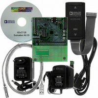
KIT DEV FOR ADUC7128
Manufacturer
Analog Devices Inc
Series
QuickStart™ PLUS Kitr
Type
MCUr
Datasheet
1.EVAL-ADUC7128QSPZ.pdf
(92 pages)
Specifications of EVAL-ADUC7128QSPZ
Contents
Evaluation Board, Power Supply, Cable, Software, Emulator and Documentation
Silicon Manufacturer
Analog Devices
Core Architecture
ARM
Core Sub-architecture
ARM7TDMI
Silicon Core Number
ADuC7128
Rohs Compliant
Yes
Lead Free Status / RoHS Status
Lead free / RoHS Compliant
For Use With/related Products
ADuC7128
Lead Free Status / RoHS Status
Lead free / RoHS Compliant, Lead free / RoHS Compliant


ADuC7128/ADuC7129
Table 8. SPI Slave Mode Timing (PHASE Mode = 0)
Parameter
t
t
t
t
t
t
t
t
t
t
t
t
1
2
CS
SL
SH
DAV
DSU
DHD
DF
DR
SR
SF
DOCS
SFS
t
t
UCLK
HCLK
= 23.9 ns. It corresponds to the 41.78 MHz internal clock from the PLL before the clock divider.
depends on the clock divider or CD bits in the PLLCON MMR, t
(POLARITY = 0)
(POLARITY = 1)
Description
CS to SCLOCK edge
SCLOCK low pulse width
SCLOCK high pulse width
Data output valid after SCLOCK edge
Data input setup time before SCLOCK edge
Data input hold time after SCLOCK edge
Data output fall time
Data output rise time
SCLOCK rise time
SCLOCK fall time
Data output valid after CS edge
CS high after SCLOCK edge
SCLOCK
SCLOCK
MISO
MOSI
CS
t
DOCS
t
CS
t
DSU
1
MSB IN
2
t
MSB
2
DHD
t
SH
Figure 9. SPI Slave Mode Timing (PHASE Mode = 0)
t
DF
t
DAV
HCLK
1
= t
t
SL
Rev. 0 | Page 14 of 92
UCLK
t
1
BIT 6 TO BIT 1
DR
BIT 6 TO BIT 1
/2
CD
.
Min
2 × t
1 × t
2 × t
0
UCLK
UCLK
UCLK
(SPIDIV + 1) × t
(SPIDIV + 1) × t
5
5
Typ
5
5
LSB IN
t
SR
LSB
HCLK
HCLK
t
SF
t
SFS
Max
2 × t
12.5
12.5
12.5
12.5
25
HCLK
+ 2 × t
UCLK
Unit
ns
ns
ns
ns
ns
ns
ns
ns
ns
ns
ns
ns
Related parts for EVAL-ADUC7128QSPZ
Image
Part Number
Description
Manufacturer
Datasheet
Request
R

Part Number:
Description:
IC, ADJ LDO REG, 1.5V TO 5V 250mA MSOP-8
Manufacturer:
Vishay
Datasheet:

Part Number:
Description:
IC, ADJ LDO REG, 1.5V TO 5V 0.6A 8-TSSOP
Manufacturer:
Vishay
Datasheet:
Part Number:
Description:
IC, ADJ LDO REG, 1.5V TO 5V 250mA MSOP-8
Manufacturer:
Vishay
Datasheet:

Part Number:
Description:
IC ADJ LDO REG 1.5V TO 5V 150mA 5-SOT-23
Manufacturer:
Vishay
Datasheet:

Part Number:
Description:
BOARD EVAL AS1324-AD
Manufacturer:
austriamicrosystems
Datasheet:
Part Number:
Description:
IC, ADJ LDO REG, 1.5V TO 5V 0.6A 8-TSSOP
Manufacturer:
Vishay
Datasheet:

Part Number:
Description:
IC, ADJ LDO REG, 1.5V TO 5V, 0.3A, MSOP8
Manufacturer:
Vishay
Datasheet:
Part Number:
Description:
IC, ADJ LDO REG, 1.5V TO 5V, 0.3A, MSOP8
Manufacturer:
Vishay
Datasheet:
Part Number:
Description:
IC, ADJ LDO REG 1.215V TO 5V 0.3A MSOP-8
Manufacturer:
Vishay
Datasheet:
Part Number:
Description:
IC, ADJ LDO REG 1.215V TO 5V 0.3A MSOP-8
Manufacturer:
Vishay
Datasheet:

Part Number:
Description:
±1.7g Dual-Axis IMEMS Accelerometer Evaluation Board
Manufacturer:
Analog Devices Inc
Datasheet:

Part Number:
Description:
IC MULTIPLIER ANALOG 8-SOIC T/R
Manufacturer:
Analog Devices Inc
Datasheet:

Part Number:
Description:
IC ANALOG MULTIPLIER 8-DIP
Manufacturer:
Analog Devices Inc
Datasheet:
Part Number:
Description:
IC ANALOG MULTIPLIER 8-SOIC
Manufacturer:
Analog Devices Inc
Datasheet:
Part Number:
Description:
IC ANALOG MULTIPLIER 8-DIP
Manufacturer:
Analog Devices Inc
Datasheet: