EVAL-ADUC7026QSPZ Analog Devices Inc, EVAL-ADUC7026QSPZ Datasheet - Page 64
EVAL-ADUC7026QSPZ
Manufacturer Part Number
EVAL-ADUC7026QSPZ
Description
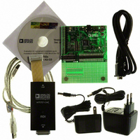
KIT DEV ADUC7026/7027 QUICK PLUS
Manufacturer
Analog Devices Inc
Series
QuickStart™ PLUS Kitr
Type
MCUr
Specifications of EVAL-ADUC7026QSPZ
Contents
Evaluation Board, Power Supply, Cable, Software, Emulator and Documentation
Silicon Manufacturer
Analog Devices
Core Architecture
ARM
Core Sub-architecture
ARM7TDMI
Silicon Core Number
ADuC7026
Rohs Compliant
Yes
Lead Free Status / RoHS Status
Lead free / RoHS Compliant
For Use With/related Products
ADuC7026
Lead Free Status / Rohs Status
Compliant
Available stocks
Company
Part Number
Manufacturer
Quantity
Price
Company:

Part Number:
EVAL-ADUC7026QSPZ
Manufacturer:
Analog Devices Inc
Quantity:
135


ADuC7019/20/21/22/24/25/26/27/28
Table 50. COMIID0 MMR Bit Descriptions
Bit 2:1
Status Bits
00
11
10
01
00
COMCON0 Register
Name
COMCON0
COMCON0 is the line control register.
Table 51. COMCON0 MMR Bit Descriptions
Bit
7
6
5
4
3
2
1:0
COMCON1 Register
Name
COMCON1
COMCON1 is the modem control register.
Name
DLAB
BRK
SP
EPS
PEN
STOP
WLS
Bit 0
NINT
1
0
0
0
0
Address
0xFFFF070C
Address
0xFFFF0710
Description
Divisor Latch Access. Set by user to enable
access to COMDIV0 and COMDIV1 registers.
Cleared by user to disable access to COMDIV0
and COMDIV1 and enable access to COMRX
and COMTX.
Set Break. Set by user to force SOUT to 0.
Cleared to operate in normal mode.
Stick Parity. Set by user to force parity to
defined values: 1 if EPS = 1 and PEN = 1,
0 if EPS = 0 and PEN = 1.
Even Parity Select Bit. Set for even parity.
Cleared for odd parity.
Parity Enable Bit. Set by user to transmit and
check the parity bit. Cleared by user for no
parity transmission or checking.
Stop Bit. Set by user to transmit 1.5 stop bits if the
word length is 5 bits or 2 stop bits if the word
length is 6 bits, 7 bits, or 8 bits. The receiver
checks the first stop bit only, regardless of the
number of stop bits selected. Cleared by user to
generate 1 stop bit in the transmitted data.
Word Length Select:
00 = 5 bits, 01 = 6 bits, 10 = 7 bits, 11 = 8 bits
Priority
–
1
2
3
4
Definition
No interrupt.
Receive Line
Status
Interrupt.
Receive Buffer
Full Interrupt.
Transmit
Buffer Empty
Interrupt.
Modem Status
Interrupt.
Default Value
0x00
Default Value
0x00
Clearing
Operation
–
Read
COMSTA0.
Read COMRX.
Write data to
COMTX or
read COMIID0.
Read
COMSTA1.
Access
R/W
Access
R/W
Rev. B | Page 64 of 92
Table 52. COMCON1 MMR Bit Descriptions
Bit
7:5
4
3
2
1
0
COMSTA0 Register
Name
COMSTA0
COMSTA0 is the line status register.
Table 53. COMSTA0 MMR Bit Descriptions
Bit
7
6
5
4
3
2
1
0
Name
LOOPBACK
PEN
STOP
RTS
DTR
Name
TEMT
THRE
BI
FE
PE
OE
DR
Address
0xFFFF0714
Description
Reserved.
COMTX Empty Status Bit. Set automatically if
COMTX is empty. Cleared automatically when
writing to COMTX.
COMTX and COMRX Empty. Set automatically if
COMTX and COMRX are empty. Cleared automati-
cally when one of the registers receives data.
Break Error. Set when SIN is held low for more than
the maximum word length. Cleared automatically.
Framing Error. Set when an invalid stop bit occurs.
Cleared automatically.
Parity Error. Set when a parity error occurs. Cleared
automatically.
Overrun Error. Set automatically if data is over-
written before being read. Cleared automatically.
Data Ready. Set automatically when COMRX is
full. Cleared by reading COMRX.
Description
Reserved.
Loop Back. Set by user to enable loopback
mode. In loop back mode, SOUT is forced
high. The modem signals are also directly
connected to the status inputs (RTS to CTS
and DTR to DSR). Cleared by user to be in
normal mode.
Parity Enable Bit. Set by user to transmit and
check the parity bit. Cleared by user for no
parity transmission or checking.
Stop Bit. Set by user to transmit 1.5 stop bits
if the word length is 5 bits, or 2 stop bits if
the word length is 6 bits, 7 bits, or 8 bits. The
receiver checks the first stop bit only,
regardless of the number of stop bits
selected. Cleared by user to generate 1 stop
bit in the transmitted data.
Request to Send. Set by user to force the RTS
output to 0. Cleared by user to force the RTS
output to 1.
Data Terminal Ready. Set by user to force the
DTR output to 0. Cleared by user to force the
DTR output to 1.
Default Value
0x60
Access
R
Related parts for EVAL-ADUC7026QSPZ
Image
Part Number
Description
Manufacturer
Datasheet
Request
R

Part Number:
Description:
IC, ADJ LDO REG, 1.5V TO 5V 250mA MSOP-8
Manufacturer:
Vishay
Datasheet:

Part Number:
Description:
IC, ADJ LDO REG, 1.5V TO 5V 0.6A 8-TSSOP
Manufacturer:
Vishay
Datasheet:
Part Number:
Description:
IC, ADJ LDO REG, 1.5V TO 5V 250mA MSOP-8
Manufacturer:
Vishay
Datasheet:

Part Number:
Description:
IC ADJ LDO REG 1.5V TO 5V 150mA 5-SOT-23
Manufacturer:
Vishay
Datasheet:

Part Number:
Description:
BOARD EVAL AS1324-AD
Manufacturer:
austriamicrosystems
Datasheet:
Part Number:
Description:
IC, ADJ LDO REG, 1.5V TO 5V 0.6A 8-TSSOP
Manufacturer:
Vishay
Datasheet:

Part Number:
Description:
IC, ADJ LDO REG, 1.5V TO 5V, 0.3A, MSOP8
Manufacturer:
Vishay
Datasheet:
Part Number:
Description:
IC, ADJ LDO REG, 1.5V TO 5V, 0.3A, MSOP8
Manufacturer:
Vishay
Datasheet:
Part Number:
Description:
IC, ADJ LDO REG 1.215V TO 5V 0.3A MSOP-8
Manufacturer:
Vishay
Datasheet:
Part Number:
Description:
IC, ADJ LDO REG 1.215V TO 5V 0.3A MSOP-8
Manufacturer:
Vishay
Datasheet:

Part Number:
Description:
±1.7g Dual-Axis IMEMS Accelerometer Evaluation Board
Manufacturer:
Analog Devices Inc
Datasheet:

Part Number:
Description:
IC MULTIPLIER ANALOG 8-SOIC T/R
Manufacturer:
Analog Devices Inc
Datasheet:

Part Number:
Description:
IC ANALOG MULTIPLIER 8-DIP
Manufacturer:
Analog Devices Inc
Datasheet:
Part Number:
Description:
IC ANALOG MULTIPLIER 8-SOIC
Manufacturer:
Analog Devices Inc
Datasheet:
Part Number:
Description:
IC ANALOG MULTIPLIER 8-DIP
Manufacturer:
Analog Devices Inc
Datasheet: