XE8000EV101 Semtech, XE8000EV101 Datasheet - Page 92
XE8000EV101
Manufacturer Part Number
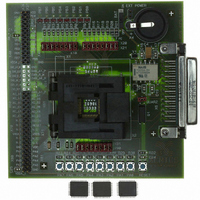
XE8000EV101
Description
EVAL BOARD FOR XE8801AMI027LF
Manufacturer
Semtech
Type
MCUr
Specifications of XE8000EV101
Contents
Fully Assembled Evaluation Board
For Use With/related Products
XE88LC01AMI027
Lead Free Status / RoHS Status
Contains lead / RoHS non-compliant


•
•
•
•
•
•
•
•
•
16.4.3
The ADC can be operated in two distinct modes: "continuous-time" and "on-request" modes (selected using the bit
CONT).
In "continuous-time" mode, the input signal is repeatedly converted into digital. After a conversion is finished, a new
one is automatically initiated. The new value is then written in the result register, and the corresponding internal
trigger pulse is generated. This operation is sketched in Figure 16-3. The conversion time in this case is defined as
T
In the "on-request" mode, the internal behaviour of the converter is the same as in the "continuous-time" mode, but
the conversion is initiated on user request (with the START bit). As shown in Figure 16-4, the conversion time is also
T
lower frequency clock than the CPU, there might be a small delay (max. 1 cycle of the ADC sampling frequency)
between the writing of the START or CONT bits and the appearance of BUSY flag.
© Semtech 2005
CONV
CONV
PGA1_GAIN: (rw) sets the gain of the first stage: 0
PGA2_GAIN: (rw) sets the gain of the second stage: 00
PGA3_GAIN: (rw) sets the gain of the third stage to PGA3_GAIN[6:0]⋅1/12.
PGA2_OFFSET: (rw) sets the offset of the second stage between –1 and +1, with increments of 0.2. The MSB gives the sign
(0 → positive, 1 → negative); amplitude is coded with the bits PGA2_OFFSET[5:0].
PGA3_OFFSET: (rw) sets the offset of the third stage between –5.25 and +5.25, with increments of 1/12. The MSB gives the
sign (0 → positive, 1 → negative); amplitude is coded with the bits PGA3_OFFSET[5:0].
BUSY: (r) set to 1 if a conversion is running. Note that the flag is set at the effective start of the conversion. Since the ADC is
generally synchronized on a lower frequency clock than the CPU, there might be a small delay (max. 1 cycle of the ADC
sampling frequency) between the writing of the START or CONT bits and the appearance of BUSY flag.
DEF: (w) sets all values to their defaults (PGA disabled, max speed, nominal modulator bias current, 2 elementary
conversions, over-sampling rate of 32) and starts a new conversion without waiting the end of the preceding one.
AMUX(4:0): (rw) AMUX[4] sets the mode (0
sets the sign (0
VMUX: (rw) sets the differential reference channel (0
.
. Note that the flag is set at the effective start of the conversion. Since the ADC is generally synchronized on a
(r = read; w = write; rw = read & write)
Continuous-Time vs. On-Request
straight, 1
cross) AMUX[2:0] sets the channel.
RegACOut[15:0]
RegACOut[15:0]
Figure 16-3. ADC "continuous-time" operation
Internal Trig
Ouput Code
Internal Trig
Ouput Code
Figure 16-4. ADC "on-request" operation
Request
START
BUSY
BUSY
IRQ
IRQ
4 differential inputs, 1
1, 1
R(1) and R(0), 1
16-7
1, 01
10.
T
T
CONV
CONV
2, 10
7 inputs with A(0) = common reference) AMUX(3)
5, 11
R(3) and R(2)).
10.
XE8801A – SX8801R
www.semtech.com
Related parts for XE8000EV101
Image
Part Number
Description
Manufacturer
Datasheet
Request
R

Part Number:
Description:
EVALUATION BOARD
Manufacturer:
Semtech
Datasheet:
Part Number:
Description:
EVALUATION BOARD
Manufacturer:
Semtech
Datasheet:
Part Number:
Description:
VOLTAGE SUPPRESSOR, TRANSIENT SEMTECH
Manufacturer:
Semtech
Datasheet:

Part Number:
Description:
HIGH VOLTAGE CAPACITORS MONOLITHIC CERAMIC TYPE
Manufacturer:
Semtech Corporation
Datasheet:
Part Number:
Description:
EZ1084CM5.0 AMP POSITIVE VOLTAGE REGULATOR
Manufacturer:
Semtech Corporation
Datasheet:
Part Number:
Description:
3.0 AMP LOW DROPOUT POSITIVE VOLTAGE REGULATORS
Manufacturer:
Semtech Corporation
Datasheet:
Part Number:
Description:
Manufacturer:
Semtech Corporation
Datasheet:
Part Number:
Description:
RailClamp Low Capacitance TVS Diode Array
Manufacturer:
Semtech Corporation
Datasheet:
Part Number:
Description:
Manufacturer:
Semtech Corporation
Datasheet:
Part Number:
Description:
Manufacturer:
Semtech Corporation
Datasheet:
Part Number:
Description:
Manufacturer:
Semtech Corporation
Datasheet:
Part Number:
Description:
Manufacturer:
Semtech Corporation
Datasheet: