DEMO9S12XEP100 Freescale Semiconductor, DEMO9S12XEP100 Datasheet - Page 489
DEMO9S12XEP100
Manufacturer Part Number
DEMO9S12XEP100
Description
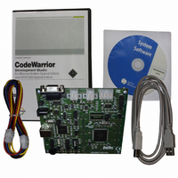
BOARD DEMO FOR MC9S12XEP100
Manufacturer
Freescale Semiconductor
Type
MCUr
Datasheet
1.EVB9S12XEP100.pdf
(1328 pages)
Specifications of DEMO9S12XEP100
Contents
Board, Cables, CD
Processor To Be Evaluated
MC9S12XEP100
Data Bus Width
16 bit
Interface Type
RS-232
Silicon Manufacturer
Freescale
Core Architecture
S12
Core Sub-architecture
S12
Silicon Core Number
MC9S12
Silicon Family Name
S12XE
Rohs Compliant
Yes
For Use With/related Products
MC9S12XEP100
Lead Free Status / RoHS Status
Lead free / RoHS Compliant
Available stocks
Company
Part Number
Manufacturer
Quantity
Price
Company:

Part Number:
DEMO9S12XEP100
Manufacturer:
PANASONIC
Quantity:
46 000
Company:
Part Number:
DEMO9S12XEP100
Manufacturer:
Freescale Semiconductor
Quantity:
135


11.4.1.1.1
The oscillator output clock signal (OSCCLK) is fed through the reference programmable divider and is
divided in a range of 1 to 64 (REFDIV+1) to output the REFCLK. The VCO output clock, (VCOCLK) is
fed back through the programmable loop divider and is divided in a range of 2 to 128 in increments of [2
x (SYNDIV +1)] to output the FBCLK. The VCOCLK is fed to the final programmable divider and is
divided in a range of 1,2,4,6,8,... to 62 (2*POSTDIV) to output the PLLCLK. See
The phase detector then compares the FBCLK, with the REFCLK. Correction pulses are generated based
on the phase difference between the two signals. The loop filter then slightly alters the DC voltage on the
internal filter capacitor, based on the width and direction of the correction pulse.
The user must select the range of the REFCLK frequency and the range of the VCOCLK frequency to
ensure that the correct IPLL loop bandwidth is set.
The lock detector compares the frequencies of the FBCLK, and the REFCLK. Therefore, the speed of the
lock detector is directly proportional to the reference clock frequency. The circuit determines the lock
condition based on this comparison.
If IPLL LOCK interrupt requests are enabled, the software can wait for an interrupt request and then check
the LOCK bit. If interrupt requests are disabled, software can poll the LOCK bit continuously (during
IPLL start-up, usually) or at periodic intervals. In either case, only when the LOCK bit is set, the PLLCLK
can be selected as the source for the system and core clocks. If the IPLL is selected as the source for the
system and core clocks and the LOCK bit is clear, the IPLL has suffered a severe noise hit and the software
must take appropriate action, depending on the application.
Freescale Semiconductor
4MHz
8MHz
4MHz
8MHz
4MHz
4MHz
4MHz
4MHz
f
Because of an order from the United States International Trade Commission, BGA-packaged product lines and partnumbers
OSC
indicated here currently are not available from Freescale for import or sale in the United States prior to September 2010
•
•
•
The LOCK bit is a read-only indicator of the locked state of the IPLL.
The LOCK bit is set when the VCO frequency is within a certain tolerance, ∆
when the VCO frequency is out of a certain tolerance, ∆
Interrupt requests can occur if enabled (LOCKIE = 1) when the lock condition changes, toggling
the LOCK bit.
REFDIV[5:0]
$01
$03
$00
$00
$00
$01
$03
$03
IPLL Operation
2MHz
2MHz
4MHz
8MHz
4MHz
2MHz
1MHz
1MHz
f
REF
REFFRQ[1:0] SYNDIV[5:0]
Table 11-14. Examples of IPLL Divider Settings
MC9S12XE-Family Reference Manual Rev. 1.23
01
01
01
10
01
01
00
00
$18
$18
$09
$04
$03
$18
$18
$31
100MHz
100MHz
100MHz
100MHz
80MHz
80MHz
32MHz
50MHz
f
VCO
Chapter 11 S12XE Clocks and Reset Generator (S12XECRGV1)
VCOFRQ[1:0] POSTDIV[4:0]
unl
.
11
11
01
01
00
11
01
11
$00
$00
$00
$00
$01
$01
$00
$01
Figure
Lock
100MHz 50 MHz
100MHz 50 MHz
, and is cleared
11-15.
80MHz
80MHz
16MHz
50MHz
50MHz
50MHz
f
PLL
40MHz
40MHz
25MHz
25MHz
25MHz
8MHz
f
BUS
489
Related parts for DEMO9S12XEP100
Image
Part Number
Description
Manufacturer
Datasheet
Request
R

Part Number:
Description:
Manufacturer:
Freescale Semiconductor, Inc
Datasheet:
Part Number:
Description:
Manufacturer:
Freescale Semiconductor, Inc
Datasheet:
Part Number:
Description:
Manufacturer:
Freescale Semiconductor, Inc
Datasheet:
Part Number:
Description:
Manufacturer:
Freescale Semiconductor, Inc
Datasheet:
Part Number:
Description:
Manufacturer:
Freescale Semiconductor, Inc
Datasheet:
Part Number:
Description:
Manufacturer:
Freescale Semiconductor, Inc
Datasheet:
Part Number:
Description:
Manufacturer:
Freescale Semiconductor, Inc
Datasheet:
Part Number:
Description:
Manufacturer:
Freescale Semiconductor, Inc
Datasheet:
Part Number:
Description:
Manufacturer:
Freescale Semiconductor, Inc
Datasheet:
Part Number:
Description:
Manufacturer:
Freescale Semiconductor, Inc
Datasheet:
Part Number:
Description:
Manufacturer:
Freescale Semiconductor, Inc
Datasheet:
Part Number:
Description:
Manufacturer:
Freescale Semiconductor, Inc
Datasheet:
Part Number:
Description:
Manufacturer:
Freescale Semiconductor, Inc
Datasheet:
Part Number:
Description:
Manufacturer:
Freescale Semiconductor, Inc
Datasheet:
Part Number:
Description:
Manufacturer:
Freescale Semiconductor, Inc
Datasheet: