DEMO9S08DZ60 Freescale Semiconductor, DEMO9S08DZ60 Datasheet - Page 279
DEMO9S08DZ60
Manufacturer Part Number
DEMO9S08DZ60
Description
BOARD DEMO
Manufacturer
Freescale Semiconductor
Type
MCUr
Datasheets
1.DEMO9S08DZ60.pdf
(416 pages)
2.DEMO9S08DZ60.pdf
(1 pages)
3.DEMO9S08DZ60.pdf
(16 pages)
4.DEMO9S08DZ60.pdf
(2 pages)
5.DEMO9S08DZ60.pdf
(1 pages)
Specifications of DEMO9S08DZ60
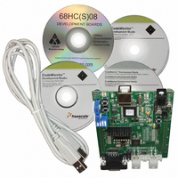
Contents
Board, Cable, CD
Processor To Be Evaluated
MC9S08DZ60
Interface Type
RS-232, USB
Silicon Manufacturer
Freescale
Core Architecture
HCS08
Core Sub-architecture
HCS08
Silicon Core Number
MC9S08
Silicon Family Name
S08D
Kit Contents
MC9S08DZ60 Board, Software, Cables, Connectors
Rohs Compliant
Yes
For Use With/related Products
MC9S08DZ60
Lead Free Status / RoHS Status
Lead free / RoHS Compliant


13.3
13.3.1
The SPI is disabled in all stop modes, regardless of the settings before executing the STOP instruction.
During either stop1 or stop2 mode, the SPI module will be fully powered down. Upon wake-up from stop1
or stop2 mode, the SPI module will be in the reset state. During stop3 mode, clocks to the SPI module are
halted. No registers are affected. If stop3 is exited with a reset, the SPI will be put into its reset state. If
stop3 is exited with an interrupt, the SPI continues from the state it was in when stop3 was entered.
13.4
The SPI has five 8-bit registers to select SPI options, control baud rate, report SPI status, and for
transmit/receive data.
Refer to the direct-page register summary in the
assignments for all SPI registers. This section refers to registers and control bits only by their names, and
a Freescale-provided equate or header file is used to translate these names into the appropriate absolute
addresses.
13.4.1
This read/write register includes the SPI enable control, interrupt enables, and configuration options.
Freescale Semiconductor
Reset
SPTIE
Field
SPIE
SPE
7
6
5
W
R
Modes of Operation
Register Definition
SPIE
SPI in Stop Modes
SPI Control Register 1 (SPIC1)
SPI Interrupt Enable (for SPRF and MODF) — This is the interrupt enable for SPI receive buffer full (SPRF)
and mode fault (MODF) events.
0 Interrupts from SPRF and MODF inhibited (use polling)
1 When SPRF or MODF is 1, request a hardware interrupt
SPI System Enable — Disabling the SPI halts any transfer that is in progress, clears data buffers, and initializes
internal state machines. SPRF is cleared and SPTEF is set to indicate the SPI transmit data buffer is empty.
0 SPI system inactive
1 SPI system enabled
SPI Transmit Interrupt Enable — This is the interrupt enable bit for SPI transmit buffer empty (SPTEF).
0 Interrupts from SPTEF inhibited (use polling)
1 When SPTEF is 1, hardware interrupt requested
0
7
SPE
0
6
Figure 13-5. SPI Control Register 1 (SPIC1)
Table 13-1. SPIC1 Field Descriptions
MC9S08DZ60 Series Data Sheet, Rev. 4
SPTIE
0
5
Memory
MSTR
0
4
Description
chapter of this data sheet for the absolute address
CPOL
3
0
Chapter 13 Serial Peripheral Interface (S08SPIV3)
CPHA
1
2
SSOE
0
1
LSBFE
0
0
279
Related parts for DEMO9S08DZ60
Image
Part Number
Description
Manufacturer
Datasheet
Request
R

Part Number:
Description:
Manufacturer:
Freescale Semiconductor, Inc
Datasheet:
Part Number:
Description:
Manufacturer:
Freescale Semiconductor, Inc
Datasheet:
Part Number:
Description:
Manufacturer:
Freescale Semiconductor, Inc
Datasheet:
Part Number:
Description:
Manufacturer:
Freescale Semiconductor, Inc
Datasheet:
Part Number:
Description:
Manufacturer:
Freescale Semiconductor, Inc
Datasheet:
Part Number:
Description:
Manufacturer:
Freescale Semiconductor, Inc
Datasheet:
Part Number:
Description:
Manufacturer:
Freescale Semiconductor, Inc
Datasheet:
Part Number:
Description:
Manufacturer:
Freescale Semiconductor, Inc
Datasheet:
Part Number:
Description:
Manufacturer:
Freescale Semiconductor, Inc
Datasheet:
Part Number:
Description:
Manufacturer:
Freescale Semiconductor, Inc
Datasheet:
Part Number:
Description:
Manufacturer:
Freescale Semiconductor, Inc
Datasheet:
Part Number:
Description:
Manufacturer:
Freescale Semiconductor, Inc
Datasheet:
Part Number:
Description:
Manufacturer:
Freescale Semiconductor, Inc
Datasheet:
Part Number:
Description:
Manufacturer:
Freescale Semiconductor, Inc
Datasheet:
Part Number:
Description:
Manufacturer:
Freescale Semiconductor, Inc
Datasheet: