DEMO9S08DZ60 Freescale Semiconductor, DEMO9S08DZ60 Datasheet - Page 340
DEMO9S08DZ60
Manufacturer Part Number
DEMO9S08DZ60
Description
BOARD DEMO
Manufacturer
Freescale Semiconductor
Type
MCUr
Datasheets
1.DEMO9S08DZ60.pdf
(416 pages)
2.DEMO9S08DZ60.pdf
(1 pages)
3.DEMO9S08DZ60.pdf
(16 pages)
4.DEMO9S08DZ60.pdf
(2 pages)
5.DEMO9S08DZ60.pdf
(1 pages)
Specifications of DEMO9S08DZ60
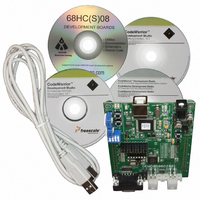
Contents
Board, Cable, CD
Processor To Be Evaluated
MC9S08DZ60
Interface Type
RS-232, USB
Silicon Manufacturer
Freescale
Core Architecture
HCS08
Core Sub-architecture
HCS08
Silicon Core Number
MC9S08
Silicon Family Name
S08D
Kit Contents
MC9S08DZ60 Board, Software, Cables, Connectors
Rohs Compliant
Yes
For Use With/related Products
MC9S08DZ60
Lead Free Status / RoHS Status
Lead free / RoHS Compliant


Chapter 16 Timer/PWM Module (S08TPMV3)
Input capture, output compare, and edge-aligned PWM functions do not make sense when the counter is
operating in up/down counting mode so this implies that all active channels within a TPM must be used in
CPWM mode when CPWMS=1.
The TPM may be used in an 8-bit MCU. The settings in the timer channel registers are buffered to ensure
coherent 16-bit updates and to avoid unexpected PWM pulse widths. Writes to any of the registers
TPMxMODH, TPMxMODL, TPMxCnVH, and TPMxCnVL, actually write to buffer registers.
In center-aligned PWM mode, the TPMxCnVH:L registers are updated with the value of their write buffer
according to the value of CLKSB:CLKSA bits, so:
When TPMxCNTH:TPMxCNTL=TPMxMODH:TPMxMODL, the TPM can optionally generate a TOF
interrupt (at the end of this count).
Writing to TPMxSC cancels any values written to TPMxMODH and/or TPMxMODL and resets the
coherency mechanism for the modulo registers. Writing to TPMxCnSC cancels any values written to the
channel value registers and resets the coherency mechanism for TPMxCnVH:TPMxCnVL.
16.5
16.5.1
The TPM is reset whenever any MCU reset occurs.
16.5.2
Reset clears the TPMxSC register which disables clocks to the TPM and disables timer overflow interrupts
(TOIE=0). CPWMS, MSnB, MSnA, ELSnB, and ELSnA are all cleared which configures all TPM
channels for input-capture operation with the associated pins disconnected from I/O pin logic (so all MCU
pins related to the TPM revert to general purpose I/O pins).
16.6
16.6.1
The TPM generates an optional interrupt for the main counter overflow and an interrupt for each channel.
The meaning of channel interrupts depends on each channel’s mode of operation. If the channel is
configured for input capture, the interrupt flag is set each time the selected input capture edge is
recognized. If the channel is configured for output compare or PWM modes, the interrupt flag is set each
time the main timer counter matches the value in the 16-bit channel value register.
340
•
•
If (CLKSB:CLKSA = 0:0), the registers are updated when the second byte is written
If (CLKSB:CLKSA not = 0:0), the registers are updated after the both bytes were written, and the
TPM counter changes from (TPMxMODH:TPMxMODL - 1) to (TPMxMODH:TPMxMODL). If
the TPM counter is a free-running counter, the update is made when the TPM counter changes from
0xFFFE to 0xFFFF.
Reset Overview
Interrupts
General
Description of Reset Operation
General
MC9S08DZ60 Series Data Sheet, Rev. 4
Freescale Semiconductor
Related parts for DEMO9S08DZ60
Image
Part Number
Description
Manufacturer
Datasheet
Request
R

Part Number:
Description:
Manufacturer:
Freescale Semiconductor, Inc
Datasheet:
Part Number:
Description:
Manufacturer:
Freescale Semiconductor, Inc
Datasheet:
Part Number:
Description:
Manufacturer:
Freescale Semiconductor, Inc
Datasheet:
Part Number:
Description:
Manufacturer:
Freescale Semiconductor, Inc
Datasheet:
Part Number:
Description:
Manufacturer:
Freescale Semiconductor, Inc
Datasheet:
Part Number:
Description:
Manufacturer:
Freescale Semiconductor, Inc
Datasheet:
Part Number:
Description:
Manufacturer:
Freescale Semiconductor, Inc
Datasheet:
Part Number:
Description:
Manufacturer:
Freescale Semiconductor, Inc
Datasheet:
Part Number:
Description:
Manufacturer:
Freescale Semiconductor, Inc
Datasheet:
Part Number:
Description:
Manufacturer:
Freescale Semiconductor, Inc
Datasheet:
Part Number:
Description:
Manufacturer:
Freescale Semiconductor, Inc
Datasheet:
Part Number:
Description:
Manufacturer:
Freescale Semiconductor, Inc
Datasheet:
Part Number:
Description:
Manufacturer:
Freescale Semiconductor, Inc
Datasheet:
Part Number:
Description:
Manufacturer:
Freescale Semiconductor, Inc
Datasheet:
Part Number:
Description:
Manufacturer:
Freescale Semiconductor, Inc
Datasheet: