P0304 Terasic Technologies Inc, P0304 Datasheet - Page 36
P0304
Manufacturer Part Number
P0304
Description
DE2-70 CALL FOR ACADEMIC PRICING
Manufacturer
Terasic Technologies Inc
Type
FPGAr
Datasheet
1.P0304.pdf
(93 pages)
Specifications of P0304
Contents
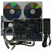
DE2-70 Board, Power Supply, Cables, Plastic cover and software
For Use With/related Products
Cyclone II 2C70
For Use With
P0033 - BOARD ADAPTER HSMC TO GPIOP0006 - BOARD ADAPTER THDB-SUMP0001 - MODULE DIGITAL CAMERA 5MP (D5M)P0307 - KIT DEV 4.3" LCD TOUCH PANEL
Lead Free Status / RoHS Status
Lead free / RoHS Compliant
Other names
DE2-70
Available stocks
Company
Part Number
Manufacturer
Quantity
Price
Company:

Part Number:
P0304UAL
Manufacturer:
Littelfuse
Quantity:
45 000
Company:
Part Number:
P0304UBL
Manufacturer:
Littelfuse
Quantity:
45 000
Company:
Part Number:
P0304UCL
Manufacturer:
Littelfuse
Quantity:
45 000


DE2-70 User Manual
There are also 18 toggle switches (sliders) on the DE2-70 board. These switches are not debounced,
and are intended for use as level-sensitive data inputs to a circuit. Each switch is connected directly
to a pin on the Cyclone II FPGA. When a switch is in the DOWN position (closest to the edge of
the board) it provides a low logic level (0 volts) to the FPGA, and when the switch is in the UP
position it provides a high logic level (3.3 volts).
There are 27 user-controllable LEDs on the DE2-70 board. Eighteen red LEDs are situated above
th
the 18 toggle switches, and eight green LEDs are found above the pushbutton switches (the 9
green LED is in the middle of the 7-segment displays). Each LED is driven directly by a pin on the
Cyclone II FPGA; driving its associated pin to a high logic level turns the LED on, and driving the
pin low turns it off. A schematic diagram that shows the pushbutton and toggle switches is given in
Figure 5.4. A schematic diagram that shows the LED circuitry appears in Figure 5.5.
A list of the pin names on the Cyclone II FPGA that are connected to the toggle switches is given in
Table 5.1. Similarly, the pins used to connect to the pushbutton switches and LEDs are displayed in
Tables 5.2 and 5.3, respectively.
Figure 5.4. Schematic diagram of the pushbutton and toggle switches.
33
Related parts for P0304
Image
Part Number
Description
Manufacturer
Datasheet
Request
R

Part Number:
Description:
MODULE DIGITAL CAMERA 5MP (D5M)
Manufacturer:
Terasic Technologies Inc
Datasheet:

Part Number:
Description:
USB BLASTER CABLE
Manufacturer:
Terasic Technologies Inc
Datasheet:

Part Number:
Description:
BOARD ADAPTER HSMC TO GPIO
Manufacturer:
Terasic Technologies Inc
Datasheet:

Part Number:
Description:
BOARD ADAPTER THDB-SUM
Manufacturer:
Terasic Technologies Inc
Datasheet:

Part Number:
Description:
KIT DEV 4.3" LCD TOUCH PANEL
Manufacturer:
Terasic Technologies Inc
Datasheet:

Part Number:
Description:
DAUGHTER BOARD AD/DA GPIO ADA
Manufacturer:
Terasic Technologies Inc

Part Number:
Description:
DAUGHTER BOARD AD/DA HSMC ADA
Manufacturer:
Terasic Technologies Inc

Part Number:
Description:
KIT MAX II MICRO
Manufacturer:
Terasic Technologies Inc
Datasheet:

Part Number:
Description:
BOARD DEV/EDUCATION ALTERA DE0
Manufacturer:
Terasic Technologies Inc
Datasheet:

Part Number:
Description:
BOARD DEV DE1 ALTERA
Manufacturer:
Terasic Technologies Inc
Datasheet:

Part Number:
Description:
DE2 CALL FOR ACADEMIC PRICING
Manufacturer:
Terasic Technologies Inc

Part Number:
Description:
MODULE DIGITAL CAMERA 1.3MP
Manufacturer:
Terasic Technologies Inc
Datasheet:

Part Number:
Description:
SENSOR CMOS 1.3MEGA (FOR P0349)
Manufacturer:
Terasic Technologies Inc
Datasheet:
Part Number:
Description:
MODULE DIGITAL CAMERA 5MP (D5M)
Manufacturer:
Terasic Technologies Inc
Datasheet: