DEMO908QB8 Freescale Semiconductor, DEMO908QB8 Datasheet
DEMO908QB8
Specifications of DEMO908QB8


Related parts for DEMO908QB8


DEMO908QB8 Summary of contents
Page 1
... Demonstration Board for Freescale MC68HC908QB8 Axiom Manufacturing • 2813 Industrial Lane • Garland, TX 75041 Email: Sales@axman.com DEMO908QB8 Web: http://www.axman.com ...
Page 2
CAUTIONARY NOTES ..............................................................................................................4 TERMINOLOGY.........................................................................................................................4 FEATURES ................................................................................................................................5 REFERENCES ...........................................................................................................................6 GETTING STARTED..................................................................................................................6 OPERATING MODES ................................................................................................................6 RUN MODE ........................................................................................................................... 6 MON08 MODE ...................................................................................................................... 7 SOFTWARE DEVELOPMENT ...................................................................................................7 MEMORY MAP ..........................................................................................................................8 DEVELOPMENT SUPPORT ......................................................................................................8 ...
Page 3
Figure 1: USB_SPEED Option Header.......................................................................................9 Figure 2: MON08 Debug Port ...................................................................................................10 Figure 3: VTST_EN Option Header ..........................................................................................10 Figure 4: PWR_SEL Option Header .........................................................................................12 Figure 5. VX_EN Option Header .............................................................................................12 Figure ...
Page 4
... EMC Information on the DEMO908QB8 board: a) This product as shipped from the factory with associated power supplies and cables, has been verified to meet with requirements FCC as a CLASS A product. ...
Page 5
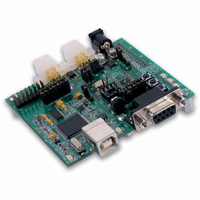
... The DEMO908QB8 is an evaluation or demonstration board for the MC68HC908QB8 micro- controller. Development of applications is quick and easy with the integrated USB-MON08, sample software tools, and examples. An optional MON08 port is also provided to allow use of a MON08 cable. A 28-pin connector allows connecting the DEMO908QB8 board to an ex- panded evaluation environment. Features: ♦ ...
Page 6
... AN2627.pdf GETTING STARTED To get started quickly, please refer to the DEMO908QB8 Quick Start Guide. This quick start will show the user how to connect the board to the PC, run a LED test program, install the cor- rect version of CodeWarrior Development Studio, and load an Analog to Digital (ATD) test pro- gram using CodeWarrior ...
Page 7
Table 1: Run Mode Setup PWR_SEL Pin2 – Pin3 (PWR) COM_SEL Pin1 – Pin3 (COM) Pin2 – Pin4 VX_EN As Required USER_EN As Required USB-MON08 All jumpers removed 4. Apply ...
Page 8
ment Studio for HC(S)08 along with the Axiom MON08 IDE for Windows for Debugging and Flash programming. A powerful source code generation tool called DriveWay™ is also provided on the ...
Page 9
... Otherwise the MCU will be forced into monitor mode out of re- set. Communications over the USB bus is controlled by the USB_SPEED header. When shipped from the factory, the DEMO908QB8 is configured for high-speed operation. If the user en- counters a communication failure, USB communication speed may be reduced by setting this option jumper to Full. ...
Page 10
MON08 Header A MON08 compatible programming cable may be attach to the 16-pin MON08 port. Use of this port requires the user to install a 2x8, 01” center, pin header. ...
Page 11
... The 16-pin socket is not installed in default configuration. POWER The DEMO908QB8 is designed to be powered from the USB_MON08 debugger during appli- cation development. A 2.0mm barrel connector has been applied to support LIN functionality and stand-alone operation. The board may also be powered through connector J1. This con- nection may also be used to supply power from the board to external circuitry ...
Page 12
PWR_SEL Figure 4: PWR_SEL Option Header PWR_SEL Power from the integrated BDM is drawn from the USB bus and is limited to 500 mA. Exces- sive current ...
Page 13
... LVI operation. TIMING The DEMO908QB8 has 2 timing sources available to the user. The internal oscillator operates at one of three, user selectable internal timing frequencies: 12.8 MHz, 8.0 MHz, or 4.0 MHz. Out of reset, the internal oscillator is set to 4MHz with a frequency tolerance of less than 25%. ...
Page 14
RS-232 An RS-232 translator provides RS-232 to TTL/CMOS logic level translation on the COM con- nector. The COM connector is a 9-pin Dsub, right-angle connector. A ferrite bead on shield ...
Page 15
... NOTE: Board must be powered from the PWR connector with V USER OPTIONS The DEMO908QB8 includes various User input and output devices to aid application develop- ment. User I/O devices include 2 momentary pushbutton switches, 2 green LEDs, 1 potenti- ometer, and 1 photocell. Each device may be enabled or disabled individually by the USER option header ...
Page 16
LED Indicators Indicators LED1 and LED2 are enabled from HC08 I/O ports by the USER option bank. Each LED is active low and illuminating when a logic low signal is ...
Page 17
... I/O PORT CONNECTOR This port connector provides access to DEMO908QB8 I/O signals. Figure 11: MCU I/O Port Connector VX 1 GND 3 PTB5/TX/AD9 5 PTB4/RX/AD8 7 PTA5/OSC1/AD3/KBI5 9 PTA4/OSC2/AD2/KBI4 11 12 PTB6/TCH2 13 14 PTB7/TCH3 15 16 PTB1/MOSI/AD5 17 18 PTB2/MISO/AD6 19 20 PTB0/SCK/AD4 21 22 PTB3/SS*/AD7 23 24 PTA0/TCH0/AD0/KBI0 25 26 PTA2/IRQ*/KBI2/TCLK 27 28 ...
Page 18
APPENDIX A Mechanical Details ...
Page 19
APPENDIX B BILL OF MATERIALS Item Qty Title 1 5 Cap, Tant, 10uF, 10V, SMB 2 1 Cap, Elect, 100uF, 16V, Alum, SMD 3 1 Cap, Elec, 10uF, 35V, Alum, ...
Page 20
Clock Osc., 9.8304Mhz, 5V, CMOS Out, SMT, 5x7mm 32 1 XTAL, 12.000MHz, 18pf, HC49/US, SMT 33 1 Res, Variable, 5K ohm, 3/8 vert adj. W/ knob 34 1 ...
Page 21
... Hdw, Stand-off, .250x.375, Hex, Alum 74 3 Hdw, Screw, 4-40x3/8, 18- NOT INSTALL COMPONENT 76 1 PCB, DEMO908QB8, 2 layer, 2.2" x 4.5", Rev D 77 ASSEMBLY 78 1 Assy, Cable, USB, A-B, 1.8 m, Black 79 1 Assy, Cable, LIN, 24in, 4pos - 4pos, Latch SU1 DO NOT INSTALL SU3 ...