DEMO908QB8 Freescale Semiconductor, DEMO908QB8 Datasheet - Page 16
DEMO908QB8
Manufacturer Part Number
DEMO908QB8
Description
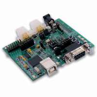
BOARD DEMO FOR MC68HC908QB8
Manufacturer
Freescale Semiconductor
Type
MCUr
Specifications of DEMO908QB8
Contents
*
Processor To Be Evaluated
MC908QB8
Data Bus Width
8 bit
Interface Type
RS-232, USB
Silicon Manufacturer
Freescale
Core Architecture
HC08
Core Sub-architecture
HC08
Silicon Core Number
MC68HC908
Silicon Family Name
HC08Q
Kit Contents
MC68HC908QB8, Cables, Guides
Rohs Compliant
No
For Use With/related Products
MC68HC908QB8
Lead Free Status / RoHS Status
Lead free / RoHS Compliant


D E M O 9 0 8 Q B 8
LED Indicators
Indicators LED1 and LED2 are enabled from HC08 I/O ports by the USER option bank. Each
LED is active low and illuminating when a logic low signal is driven from the respective MCU
I/O port. MCU ports PTB6 and PTB7 drive LED1 and LED2 respectively. The table below
details the user jumper settings.
Potentiometer
A 5k Ω, thumb-wheel type, potentiometer at RV1 provides variable resistance input for user
applications. The output is the result of a voltage divider that changes as the thumb-wheel is
turned. This device is connected to the MCU on signal PTA0. The table below details the user
jumper settings.
The potentiometer is not available while in monitor mode. Using the potentiometer requires
disabling the MON08 COM signal. This requires removing USB-MON08 Enable jumper ‘D’.
Otherwise results may be unpredictable.
Photocell
A photoconductive photocell provides light sensitive, variable resistance input for user applica-
tions. Device resistance is inversely proportional to light intensity incident on the surface of the
device. A rail-to-rail OP amp at U2 boosts the photocell output to useable levels. This signal
is available to the MCU on signal PTA1. The table below details the user jumper settings.
Table 5: User Option Jumper Settings
NOTE: User-5 option jumper must be removed to enter monitor mode.
NOTE: USB-MON08 ENABLE-D jumper must be removed to use this function.
NOTE: User-6 option jumper must be removed to enter monitor mode. The jumper may be
NOTE: USER-5 and USER-6 must be disabled to enter Monitor mode
Jumper
User-1
User-2
User-3
User-4
User-5
User-6
reinstalled after RESET.
On
Enable SW1
Enable SW2
Enable LED1
Enable LED2
Enable RV1
Enable RZ1
16
Off
Disable SW1
Disable SW2
Disable LED1
Disable LED2
Disable RV1
Disable RZ1
MCU PORT
PTA5 (U1-4)
PTA4 (U1-5)
PTB6 (U1-3)
PTB7 (U1-2)
PTA0 (U1-13)
PTA1 (U1-12)
M A R C H
1 8 ,
2 0 0 5
Related parts for DEMO908QB8
Image
Part Number
Description
Manufacturer
Datasheet
Request
R

Part Number:
Description:
Manufacturer:
STMicroelectronics
Datasheet:

Part Number:
Description:
DEMO BOARD FOR HMC6042/HMC1041Z
Manufacturer:
Honeywell Microelectronics & Precision Sensors

Part Number:
Description:
DEMO BOARD FOR HMC1042L/HMC1041Z
Manufacturer:
Honeywell Microelectronics & Precision Sensors
Datasheet:

Part Number:
Description:
KIT DEMO 4 SENSOR CHAN RS232
Manufacturer:
VTI Technologies
Datasheet:


Part Number:
Description:
DEMO: DC Power Supply, 32 Volts, 3 Amps
Manufacturer:
Tektronix
Part Number:
Description:
DEMO: Programmable DC Power Supply, 32 Volts, 3 Amps
Manufacturer:
Tektronix

Part Number:
Description:
Manufacturer:
Freescale Semiconductor, Inc
Datasheet:
Part Number:
Description:
Manufacturer:
Freescale Semiconductor, Inc
Datasheet:
Part Number:
Description:
Manufacturer:
Freescale Semiconductor, Inc
Datasheet:
Part Number:
Description:
Manufacturer:
Freescale Semiconductor, Inc
Datasheet:
Part Number:
Description:
Manufacturer:
Freescale Semiconductor, Inc
Datasheet:
Part Number:
Description:
Manufacturer:
Freescale Semiconductor, Inc
Datasheet:
Part Number:
Description:
Manufacturer:
Freescale Semiconductor, Inc
Datasheet:
Part Number:
Description:
Manufacturer:
Freescale Semiconductor, Inc
Datasheet: