DEMO908QB8 Freescale Semiconductor, DEMO908QB8 Datasheet - Page 11
DEMO908QB8
Manufacturer Part Number
DEMO908QB8
Description
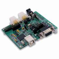
BOARD DEMO FOR MC68HC908QB8
Manufacturer
Freescale Semiconductor
Type
MCUr
Specifications of DEMO908QB8
Contents
*
Processor To Be Evaluated
MC908QB8
Data Bus Width
8 bit
Interface Type
RS-232, USB
Silicon Manufacturer
Freescale
Core Architecture
HC08
Core Sub-architecture
HC08
Silicon Core Number
MC68HC908
Silicon Family Name
HC08Q
Kit Contents
MC68HC908QB8, Cables, Guides
Rohs Compliant
No
For Use With/related Products
MC68HC908QB8
Lead Free Status / RoHS Status
Lead free / RoHS Compliant


D E M O 9 0 8 Q B 8
M A R C H
1 8 ,
2 0 0 5
MCU PACKAGE OPTIONS
The DEMO908QB8 provides footprint locations for 3 different packages. Only 1 target MCU
package may be installed at a time. Applicable signals are routed to all target MCU loca-
tions. Installing multiple packages simultaneously will cause signal corruption and may result
in damage to the device.
A 16-pin TSSOP package is installed during the manufacturing process. The board also pro-
vides an 8-pin socket and a footprint for a 16-pin socket. The 16-pin socket is not installed in
default configuration.
POWER
The DEMO908QB8 is designed to be powered from the USB_MON08 debugger during appli-
cation development. A 2.0mm barrel connector has been applied to support LIN functionality
and stand-alone operation. The board may also be powered through connector J1. This con-
nection may also be used to supply power from the board to external circuitry.
During application development, the board draws power from the USB bus through the inte-
grated UBS-MON08 connector. Total current consumption, of the board and connected cir-
cuitry, must be limited to less than 500 mA. Excessive current drain will violate the USB speci-
fication and may damage the board or the host PC. At minimum, USB bus violations will
cause the host PC to reboot sporadically.
A 2.0 mm barrel connector input has been provided to the user to support LIN functionality and
allow stand-alone operation. Voltage input at this connector must be limited to between +6V
and +18V. Voltage regulators VR1 and VR2 outputs will shut down if the connected circuit
draws excessive current. Stand-alone operation is supported though connector J1 but power
input on this connector will not support LIN functionality.
POWER SELECT
Power may be applied to the board through the integrated USB-MON08 circuitry, a 2.0mm bar-
rel connector, or through connector J1. Power selection is achieved by using 2 separate op-
tion headers: PWR_SEL option header and the VX_EN option header.
The PWR_SEL option header selects power input either from the integrated USB-MON08 cir-
cuitry or from the on-board voltage regulator. Pin 1 connects to the power output from the in-
tegrated BDM. Pin 3 connects to the on-board voltage regulator output. Pin 2 provides power
to the target board voltage rail. The figure below details the PWR_SEL header connections.
11
Related parts for DEMO908QB8
Image
Part Number
Description
Manufacturer
Datasheet
Request
R

Part Number:
Description:
Manufacturer:
STMicroelectronics
Datasheet:

Part Number:
Description:
DEMO BOARD FOR HMC6042/HMC1041Z
Manufacturer:
Honeywell Microelectronics & Precision Sensors

Part Number:
Description:
DEMO BOARD FOR HMC1042L/HMC1041Z
Manufacturer:
Honeywell Microelectronics & Precision Sensors
Datasheet:

Part Number:
Description:
KIT DEMO 4 SENSOR CHAN RS232
Manufacturer:
VTI Technologies
Datasheet:


Part Number:
Description:
DEMO: DC Power Supply, 32 Volts, 3 Amps
Manufacturer:
Tektronix
Part Number:
Description:
DEMO: Programmable DC Power Supply, 32 Volts, 3 Amps
Manufacturer:
Tektronix

Part Number:
Description:
Manufacturer:
Freescale Semiconductor, Inc
Datasheet:
Part Number:
Description:
Manufacturer:
Freescale Semiconductor, Inc
Datasheet:
Part Number:
Description:
Manufacturer:
Freescale Semiconductor, Inc
Datasheet:
Part Number:
Description:
Manufacturer:
Freescale Semiconductor, Inc
Datasheet:
Part Number:
Description:
Manufacturer:
Freescale Semiconductor, Inc
Datasheet:
Part Number:
Description:
Manufacturer:
Freescale Semiconductor, Inc
Datasheet:
Part Number:
Description:
Manufacturer:
Freescale Semiconductor, Inc
Datasheet:
Part Number:
Description:
Manufacturer:
Freescale Semiconductor, Inc
Datasheet: