DEMO908QB8 Freescale Semiconductor, DEMO908QB8 Datasheet - Page 9
DEMO908QB8
Manufacturer Part Number
DEMO908QB8
Description
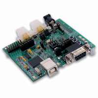
BOARD DEMO FOR MC68HC908QB8
Manufacturer
Freescale Semiconductor
Type
MCUr
Specifications of DEMO908QB8
Contents
*
Processor To Be Evaluated
MC908QB8
Data Bus Width
8 bit
Interface Type
RS-232, USB
Silicon Manufacturer
Freescale
Core Architecture
HC08
Core Sub-architecture
HC08
Silicon Core Number
MC68HC908
Silicon Family Name
HC08Q
Kit Contents
MC68HC908QB8, Cables, Guides
Rohs Compliant
No
For Use With/related Products
MC68HC908QB8
Lead Free Status / RoHS Status
Lead free / RoHS Compliant


D E M O 9 0 8 Q B 8
configuration and may be installed by the user if necessary. Note that when using an external
MON08 cable, all jumpers on the USB-MON08 ENABLE header must be removed.
Integrated MON08
The DEMO908QB8 board features an integrated USB-MON08 debugger from P&E Microcom-
puter Systems. The integrated debugger supports application development and debugging via
the internal monitor. All necessary signals, including high-voltage, clock, data, and configura-
tion signals, are provided by the integrated debugger. A USB, type B, connector provides
connection from the target board to the host PC.
The integrated debugger provides +5V power and ground to target board eliminating the need
to power the board externally. Power from the USB-MON08 is derived from the USB bus;
therefore, total current consumption for the target board, and connected circuitry, must not ex-
ceed 500mA. Excessive current drain will violate the USB specification. Damage to the host
PC USB hub or the target board may result.
A 16-pin header (USB-MON08 ENABLE) allows disconnecting the integrated debugger from
the target board. This allows the stand-alone operation of the target board. In stand-alone
operation, the target board must be power from connector J1 or the PWR connector. The Ta-
ble below details the function of the USB-MON08 Enable header.
Table 4: USB-MON08 Enable Header
Communications over the USB bus is controlled by the USB_SPEED header. When shipped
from the factory, the DEMO908QB8 is configured for high-speed operation. If the user en-
counters a communication failure, USB communication speed may be reduced by setting this
option jumper to Full.
Figure 1: USB_SPEED Option Header
NOTE: To use the board in stand-alone operation when powered from the USB cable, remove
CAUTION: Do not allow current drain to exceed 500mA when
HIGH
the shunt at position “B”. Otherwise the MCU will be forced into monitor mode out of re-
set.
USB_SPEED
1
E
D
C
B
J
F
I
powered from the USB-MON-08 BDM
2
14
12
10
8
6
4
2
3
13
11
9
7
5
3
1
FULL
Jumper On
Enabled
Enabled
Enabled
Enabled
Enabled
Enabled
Enabled
Configuration:
1 – 2: Selects USB High-speed communications
2 – 3: Selects USB Full-speed communications
Jumper Off
Disabled
Disabled
Disabled
Disabled
Disabled
Disabled
Disabled
9
Signal
VB (V out)
PTA3/RST*
PTA1/TCH1
PTA4/OSC2
PTA0/TCH0
PTA5/OSC1
PTA2/IRQ*
M A R C H
1 8 ,
2 0 0 5
Related parts for DEMO908QB8
Image
Part Number
Description
Manufacturer
Datasheet
Request
R

Part Number:
Description:
Manufacturer:
STMicroelectronics
Datasheet:

Part Number:
Description:
DEMO BOARD FOR HMC6042/HMC1041Z
Manufacturer:
Honeywell Microelectronics & Precision Sensors

Part Number:
Description:
DEMO BOARD FOR HMC1042L/HMC1041Z
Manufacturer:
Honeywell Microelectronics & Precision Sensors
Datasheet:

Part Number:
Description:
KIT DEMO 4 SENSOR CHAN RS232
Manufacturer:
VTI Technologies
Datasheet:


Part Number:
Description:
DEMO: DC Power Supply, 32 Volts, 3 Amps
Manufacturer:
Tektronix
Part Number:
Description:
DEMO: Programmable DC Power Supply, 32 Volts, 3 Amps
Manufacturer:
Tektronix

Part Number:
Description:
Manufacturer:
Freescale Semiconductor, Inc
Datasheet:
Part Number:
Description:
Manufacturer:
Freescale Semiconductor, Inc
Datasheet:
Part Number:
Description:
Manufacturer:
Freescale Semiconductor, Inc
Datasheet:
Part Number:
Description:
Manufacturer:
Freescale Semiconductor, Inc
Datasheet:
Part Number:
Description:
Manufacturer:
Freescale Semiconductor, Inc
Datasheet:
Part Number:
Description:
Manufacturer:
Freescale Semiconductor, Inc
Datasheet:
Part Number:
Description:
Manufacturer:
Freescale Semiconductor, Inc
Datasheet:
Part Number:
Description:
Manufacturer:
Freescale Semiconductor, Inc
Datasheet: