DEMO908QB8 Freescale Semiconductor, DEMO908QB8 Datasheet - Page 13
DEMO908QB8
Manufacturer Part Number
DEMO908QB8
Description
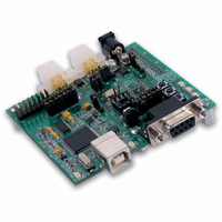
BOARD DEMO FOR MC68HC908QB8
Manufacturer
Freescale Semiconductor
Type
MCUr
Specifications of DEMO908QB8
Contents
*
Processor To Be Evaluated
MC908QB8
Data Bus Width
8 bit
Interface Type
RS-232, USB
Silicon Manufacturer
Freescale
Core Architecture
HC08
Core Sub-architecture
HC08
Silicon Core Number
MC68HC908
Silicon Family Name
HC08Q
Kit Contents
MC68HC908QB8, Cables, Guides
Rohs Compliant
No
For Use With/related Products
MC68HC908QB8
Lead Free Status / RoHS Status
Lead free / RoHS Compliant


D E M O 9 0 8 Q B 8
RESET SWITCH
The RESET switch provides a method to apply an asynchronous RESET to the MCU. The
RESET switch is connected directly to the RST* input on the MCU. Pressing the RESET
switch applies a low voltage level to the RST* input. A pull-up bias resistor on the RST* input
allows normal MCU operation. Shunt capacitance ensures an adequate input pulse width.
LOW VOLTAGE INHIBIT
The MC68HC908QB8 utilizes an internal Low Voltage Inhibit (LVI) protect against under-
voltage conditions. The LVI is enabled for 2.2Voperation out of RESET. The user must con-
figure the LVI for +5V operation is this feature is to be used. Consult the MC68HC908QB8
reference manual for details on configuring LVI operation.
TIMING
The DEMO908QB8 has 2 timing sources available to the user. The internal oscillator operates
at one of three, user selectable internal timing frequencies: 12.8 MHz, 8.0 MHz, or 4.0 MHz.
Out of reset, the internal oscillator is set to 4MHz with a frequency tolerance of less than 25%.
An 8-bit register allows trimming the internal oscillator to a tolerance of 0.4%. Refer to the
MC68HC908QB8 data sheet for details on internal oscillator operation.
An alternate clock oscillator has also been provided. An option jumper enables/disables the
use of the external oscillator to the MCU. The external oscillator is connected to PTA5 on the
MCU. The user must configure the MCU for operation with the external clock source. Refer to
the MC68HC908QB8 data sheet for details.
The alternate clock oscillator input is not installed in default configuration. Refer to the board
schematic to populate this option and associated circuitry.
Figure 6: J6 Option Header
COMMUNICATIONS
The DEMO908QB8 board provides a single Enhanced Serial Communications Interface
(ESCI) port. The ESCI port may be configured for RS-232 serial communications or for LIN
serial communications. RS-232 communications are supported through a DB9 connector. LIN
communications are supported through a pair of 4-pin Molex connectors.
The COM_SEL option header selects the communications protocol applied by the user.
NOTE: This option header is not installed in default configuration.
1
2
OFF
ON
Enables Clock Oscillator Input to MCU
Disables Clock Oscillator Input to MCU
13
M A R C H
1 8 ,
2 0 0 5
Related parts for DEMO908QB8
Image
Part Number
Description
Manufacturer
Datasheet
Request
R

Part Number:
Description:
Manufacturer:
STMicroelectronics
Datasheet:

Part Number:
Description:
DEMO BOARD FOR HMC6042/HMC1041Z
Manufacturer:
Honeywell Microelectronics & Precision Sensors

Part Number:
Description:
DEMO BOARD FOR HMC1042L/HMC1041Z
Manufacturer:
Honeywell Microelectronics & Precision Sensors
Datasheet:

Part Number:
Description:
KIT DEMO 4 SENSOR CHAN RS232
Manufacturer:
VTI Technologies
Datasheet:


Part Number:
Description:
DEMO: DC Power Supply, 32 Volts, 3 Amps
Manufacturer:
Tektronix
Part Number:
Description:
DEMO: Programmable DC Power Supply, 32 Volts, 3 Amps
Manufacturer:
Tektronix

Part Number:
Description:
Manufacturer:
Freescale Semiconductor, Inc
Datasheet:
Part Number:
Description:
Manufacturer:
Freescale Semiconductor, Inc
Datasheet:
Part Number:
Description:
Manufacturer:
Freescale Semiconductor, Inc
Datasheet:
Part Number:
Description:
Manufacturer:
Freescale Semiconductor, Inc
Datasheet:
Part Number:
Description:
Manufacturer:
Freescale Semiconductor, Inc
Datasheet:
Part Number:
Description:
Manufacturer:
Freescale Semiconductor, Inc
Datasheet:
Part Number:
Description:
Manufacturer:
Freescale Semiconductor, Inc
Datasheet:
Part Number:
Description:
Manufacturer:
Freescale Semiconductor, Inc
Datasheet: