DEMO908QB8 Freescale Semiconductor, DEMO908QB8 Datasheet - Page 10
DEMO908QB8
Manufacturer Part Number
DEMO908QB8
Description
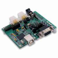
BOARD DEMO FOR MC68HC908QB8
Manufacturer
Freescale Semiconductor
Type
MCUr
Specifications of DEMO908QB8
Contents
*
Processor To Be Evaluated
MC908QB8
Data Bus Width
8 bit
Interface Type
RS-232, USB
Silicon Manufacturer
Freescale
Core Architecture
HC08
Core Sub-architecture
HC08
Silicon Core Number
MC68HC908
Silicon Family Name
HC08Q
Kit Contents
MC68HC908QB8, Cables, Guides
Rohs Compliant
No
For Use With/related Products
MC68HC908QB8
Lead Free Status / RoHS Status
Lead free / RoHS Compliant


D E M O 9 0 8 Q B 8
MON08 Header
A MON08 compatible programming cable may be attach to the 16-pin MON08 port. Use of
this port requires the user to install a 2x8, 01” center, pin header. When using the MON08
programming cable, the VTST_EN option jumper forces the MCU to enter monitor mode.
Some MON08 cables can supply VTST directly eliminating the need to set the VTST_EN
option jumper. The MCU supports monitor mode communications at 9600 bps. Refer to
MC68HC908QB8 documentation for further details.
Figure 2: MON08 Debug Port
VTST_EN
The VTST_EN circuitry allows the user to force the target MCU into monitor mode. This cir-
cuitry is not installed in default configuration but is described here to allow the user to install if
needed. Refer to the board schematic to install this circuit functionality if necessary.
When using an unpowered external MON08 programming cable, the VTST _EN jumper (J5)
enables the high voltage input necessary to force the MCU into monitor mode. A zener diode
at D1 sets the appropriate voltage level on the MCU IRQ* signal line. Use of an external
MON08 programming cable requires voltage input at the PWR connector greater than +9V.
Figure 3: VTST_EN Option Header
NOTE: When using and external MON08 cable, disable the integrated USB-MON08 debugger
NOTE: This header is not installed in default configuration.
NOTE: This header is not installed in default configuration.
NOTE: Use of this option requires +9VDC input on PWR connector or use of self-powered BDM
PTA5/OSC1 13 14
•
by removing all jumpers on the USB-MON08 ENABLE header.
cable.
• OFF
ON
V
DD
11 12 PTA1
15 16
1
3
5
7
9
IRQ* signal line set to 8.2V. MON08 monitor mode enabled
IRQ* signal line pulled up to V
10 PTA4
2 GND
4 PTA3/RST*
6 PTA2/IRQ*
8 PTA0
10
DD
See the HC08 Reference Manual for
complete MON08 documentation
. MON08 monitor mode disabled
M A R C H
1 8 ,
2 0 0 5
Related parts for DEMO908QB8
Image
Part Number
Description
Manufacturer
Datasheet
Request
R

Part Number:
Description:
Manufacturer:
STMicroelectronics
Datasheet:

Part Number:
Description:
DEMO BOARD FOR HMC6042/HMC1041Z
Manufacturer:
Honeywell Microelectronics & Precision Sensors

Part Number:
Description:
DEMO BOARD FOR HMC1042L/HMC1041Z
Manufacturer:
Honeywell Microelectronics & Precision Sensors
Datasheet:

Part Number:
Description:
KIT DEMO 4 SENSOR CHAN RS232
Manufacturer:
VTI Technologies
Datasheet:


Part Number:
Description:
DEMO: DC Power Supply, 32 Volts, 3 Amps
Manufacturer:
Tektronix
Part Number:
Description:
DEMO: Programmable DC Power Supply, 32 Volts, 3 Amps
Manufacturer:
Tektronix

Part Number:
Description:
Manufacturer:
Freescale Semiconductor, Inc
Datasheet:
Part Number:
Description:
Manufacturer:
Freescale Semiconductor, Inc
Datasheet:
Part Number:
Description:
Manufacturer:
Freescale Semiconductor, Inc
Datasheet:
Part Number:
Description:
Manufacturer:
Freescale Semiconductor, Inc
Datasheet:
Part Number:
Description:
Manufacturer:
Freescale Semiconductor, Inc
Datasheet:
Part Number:
Description:
Manufacturer:
Freescale Semiconductor, Inc
Datasheet:
Part Number:
Description:
Manufacturer:
Freescale Semiconductor, Inc
Datasheet:
Part Number:
Description:
Manufacturer:
Freescale Semiconductor, Inc
Datasheet: