MCIMX31LITEKITC Freescale Semiconductor, MCIMX31LITEKITC Datasheet - Page 104
MCIMX31LITEKITC
Manufacturer Part Number
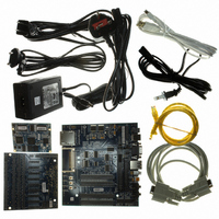
MCIMX31LITEKITC
Description
BOARD DEV FOR I.MX31
Manufacturer
Freescale Semiconductor
Type
MCUr
Datasheet
1.MCIMX31LITEKITC.pdf
(122 pages)
Specifications of MCIMX31LITEKITC
Contents
Module and Misc Hardware
For Use With/related Products
i.MX31
Lead Free Status / RoHS Status
Lead free / RoHS Compliant


Electrical Characteristics
4.3.23
This section describes the electrical information of the USBOTG port. The OTG port supports both serial
and parallel interfaces.
The high speed (HS) interface is supported via the ULPI (Ultra Low Pin Count Interface).
depicts the USB ULPI timing diagram, and
104
1
Setup time (control in, 8-bit data in)
Hold time (control in, 8-bit data in)
Output delay (control out, 8-bit data out)
Timing parameters are given as viewed by transceiver side.
USB Electrical Specifications
Control in (dir, nxt)
Control out (stp)
Table 63. SSI Receiver with External Clock Timing Parameters (continued)
SS28
SS30
SS32
SS34
SS35
SS36
SS40
SS41
ID
Data out
Data in
Clock
(Rx) CK high to FS (bl) high
(Rx) CK high to FS (bl) low
(Rx) CK high to FS (wl) high
(Rx) CK high to FS (wl) low
(Tx/Rx) External FS rise time
(Tx/Rx) External FS fall time
SRXD setup time before (Rx) CK low
SRXD hold time after (Rx) CK low
Parameter
Table 64. USB ULPI Interface Timing Specification
T
Figure 85. USB ULPI Interface Timing Diagram
T
SD
SC
MCIMX31/MCIMX31L Technical Data, Rev. 4.1
Parameter
Table 64
T
T
HC
HD
T
T
lists the timing parameters.
DC
DD
T
T
T
Symbol
–10.0
–10.0
HC
DC
SC
10.0
10.0
10.0
Min
2.0
—
—
, T
, T
, T
SD
HD
DD
Max
15.0
15.0
6.0
6.0
1
—
—
—
—
Min
—
6
0
Freescale Semiconductor
Unit
ns
ns
ns
ns
ns
ns
ns
ns
Max
—
—
9
T
DC
Figure 85
Units
ns
ns
ns
Related parts for MCIMX31LITEKITC
Image
Part Number
Description
Manufacturer
Datasheet
Request
R

Part Number:
Description:
Multimedia Applications Processors
Manufacturer:
FREESCALE [Freescale Semiconductor, Inc]
Datasheet:

Part Number:
Description:
Manufacturer:
Freescale Semiconductor, Inc
Datasheet:
Part Number:
Description:
Manufacturer:
Freescale Semiconductor, Inc
Datasheet:
Part Number:
Description:
Manufacturer:
Freescale Semiconductor, Inc
Datasheet:
Part Number:
Description:
Manufacturer:
Freescale Semiconductor, Inc
Datasheet:
Part Number:
Description:
Manufacturer:
Freescale Semiconductor, Inc
Datasheet:
Part Number:
Description:
Manufacturer:
Freescale Semiconductor, Inc
Datasheet:
Part Number:
Description:
Manufacturer:
Freescale Semiconductor, Inc
Datasheet:
Part Number:
Description:
Manufacturer:
Freescale Semiconductor, Inc
Datasheet:
Part Number:
Description:
Manufacturer:
Freescale Semiconductor, Inc
Datasheet:
Part Number:
Description:
Manufacturer:
Freescale Semiconductor, Inc
Datasheet:
Part Number:
Description:
Manufacturer:
Freescale Semiconductor, Inc
Datasheet:
Part Number:
Description:
Manufacturer:
Freescale Semiconductor, Inc
Datasheet:
Part Number:
Description:
Manufacturer:
Freescale Semiconductor, Inc
Datasheet:
Part Number:
Description:
Manufacturer:
Freescale Semiconductor, Inc
Datasheet: