C8051F902-GU Silicon Laboratories Inc, C8051F902-GU Datasheet - Page 190
C8051F902-GU
Manufacturer Part Number
C8051F902-GU
Description
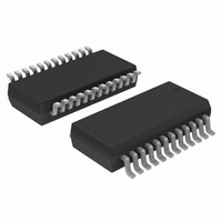
IC MCU 8BIT 8KB FLASH 24QSOP
Manufacturer
Silicon Laboratories Inc
Series
C8051F9xxr
Specifications of C8051F902-GU
Program Memory Type
FLASH
Program Memory Size
8KB (8K x 8)
Package / Case
24-QSOP
Core Processor
8051
Core Size
8-Bit
Speed
25MHz
Connectivity
SMBus (2-Wire/I²C), SPI, UART/USART
Peripherals
Brown-out Detect/Reset, POR, PWM, Temp Sensor, WDT
Number Of I /o
16
Ram Size
768 x 8
Voltage - Supply (vcc/vdd)
0.9 V ~ 3.6 V
Data Converters
A/D 15x10/12b
Oscillator Type
Internal
Operating Temperature
-40°C ~ 85°C
Processor Series
C8051F9x
Core
8051
Data Ram Size
768 B
Interface Type
UART
Maximum Clock Frequency
25 MHz
Number Of Timers
4
Operating Supply Voltage
0.9 V to 3.6 V
Maximum Operating Temperature
+ 85 C
Mounting Style
SMD/SMT
3rd Party Development Tools
PK51, CA51, A51, ULINK2
Development Tools By Supplier
C8051F912DK
Minimum Operating Temperature
- 40 C
On-chip Adc
12 bit
Package
24QSOP
Device Core
8051
Family Name
C8051F90x
Maximum Speed
25 MHz
Data Bus Width
8 Bit
Number Of Programmable I/os
16
Lead Free Status / RoHS Status
Lead free / RoHS Compliant
Eeprom Size
-
Lead Free Status / Rohs Status
Lead free / RoHS Compliant
Other names
336-1849-5
Available stocks
Company
Part Number
Manufacturer
Quantity
Price
Company:

Part Number:
C8051F902-GU
Manufacturer:
SEMIKRON
Quantity:
45
Company:
Part Number:
C8051F902-GU
Manufacturer:
Silicon Laboratories Inc
Quantity:
135


C8051F91x-C8051F90x
20.1.2. Using RTC0ADR and RTC0DAT to Access SmaRTClock Internal Registers
The SmaRTClock internal registers can be read and written using RTC0ADR and RTC0DAT. The
RTC0ADR register selects the SmaRTClock internal register that will be targeted by subsequent reads or
writes. Recommended instruction timing is provided in this section. If the recommended instruction timing
is not followed, then BUSY (RTC0ADR.7) should be checked prior to each read or write operation to make
sure the SmaRTClock Interface is not busy performing the previous read or write operation. A
SmaRTClock Write operation is initiated by writing to the RTC0DAT register. Below is an example of
writing to a SmaRTClock internal register.
A SmaRTClock Read operation is initiated by setting the SmaRTClock Interface Busy bit. This transfers
the contents of the internal register selected by RTC0ADR to RTC0DAT. The transferred data will remain in
RTC0DAT until the next read or write operation. Below is an example of reading a SmaRTClock internal
register.
Note: The RTC0ADR and RTC0DAT registers will retain their state upon a device reset.
20.1.3. RTC0ADR Short Strobe Feature
Reads and writes to indirect SmaRTClock registers normally take 7 system clock cycles. To minimize the
indirect register access time, the Short Strobe feature decreases the read and write access time to 6
system clocks. The Short Strobe feature is automatically enabled on reset and can be manually
enabled/disabled using the SHORT (RTC0ADR.4) control bit.
Recommended Instruction Timing for a single register read with short strobe enabled:
mov RTC0ADR, #095h
nop
nop
nop
mov A, RTC0DAT
Recommended Instruction Timing for a single register write with short strobe enabled:
mov RTC0ADR, #095h
mov RTC0DAT, #000h
nop
20.1.4. SmaRTClock Interface Autoread Feature
When Autoread is enabled, each read from RTC0DAT initiates the next indirect read operation on the
SmaRTClock internal register selected by RTC0ADR. Software should set the BUSY bit once at the
beginning of each series of consecutive reads. Software should follow recommended instruction timing or
check if the SmaRTClock Interface is busy prior to reading RTC0DAT. Autoread is enabled by setting
AUTORD (RTC0ADR.6) to logic 1.
190
1. Poll BUSY (RTC0ADR.7) until it returns 0 or follow recommended instruction timing.
2. Write 0x05 to RTC0ADR. This selects the internal RTC0CN register at SmaRTClock Address
3. Write 0x00 to RTC0DAT. This operation writes 0x00 to the internal RTC0CN register.
1. Poll BUSY (RTC0ADR.7) until it returns 0 or follow recommended instruction timing.
2. Write 0x05 to RTC0ADR. This selects the internal RTC0CN register at SmaRTClock Address
3. Write 1 to BUSY. This initiates the transfer of data from RTC0CN to RTC0DAT.
4. Poll BUSY (RTC0ADR.7) until it returns 0 or follow recommend instruction timing.
5. Read data from RTC0DAT. This data is a copy of the RTC0CN register.
0x05.
0x05.
Rev. 1.0
Related parts for C8051F902-GU
Image
Part Number
Description
Manufacturer
Datasheet
Request
R

Part Number:
Description:
SMD/C°/SINGLE-ENDED OUTPUT SILICON OSCILLATOR
Manufacturer:
Silicon Laboratories Inc
Part Number:
Description:
Manufacturer:
Silicon Laboratories Inc
Datasheet:
Part Number:
Description:
N/A N/A/SI4010 AES KEYFOB DEMO WITH LCD RX
Manufacturer:
Silicon Laboratories Inc
Datasheet:
Part Number:
Description:
N/A N/A/SI4010 SIMPLIFIED KEY FOB DEMO WITH LED RX
Manufacturer:
Silicon Laboratories Inc
Datasheet:
Part Number:
Description:
N/A/-40 TO 85 OC/EZLINK MODULE; F930/4432 HIGH BAND (REV E/B1)
Manufacturer:
Silicon Laboratories Inc
Part Number:
Description:
EZLink Module; F930/4432 Low Band (rev e/B1)
Manufacturer:
Silicon Laboratories Inc
Part Number:
Description:
I°/4460 10 DBM RADIO TEST CARD 434 MHZ
Manufacturer:
Silicon Laboratories Inc
Part Number:
Description:
I°/4461 14 DBM RADIO TEST CARD 868 MHZ
Manufacturer:
Silicon Laboratories Inc
Part Number:
Description:
I°/4463 20 DBM RFSWITCH RADIO TEST CARD 460 MHZ
Manufacturer:
Silicon Laboratories Inc
Part Number:
Description:
I°/4463 20 DBM RADIO TEST CARD 868 MHZ
Manufacturer:
Silicon Laboratories Inc
Part Number:
Description:
I°/4463 27 DBM RADIO TEST CARD 868 MHZ
Manufacturer:
Silicon Laboratories Inc
Part Number:
Description:
I°/4463 SKYWORKS 30 DBM RADIO TEST CARD 915 MHZ
Manufacturer:
Silicon Laboratories Inc
Part Number:
Description:
N/A N/A/-40 TO 85 OC/4463 RFMD 30 DBM RADIO TEST CARD 915 MHZ
Manufacturer:
Silicon Laboratories Inc
Part Number:
Description:
I°/4463 20 DBM RADIO TEST CARD 169 MHZ
Manufacturer:
Silicon Laboratories Inc