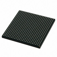
MCIMX512CJM6C Freescale Semiconductor, MCIMX512CJM6C Datasheet - Page 5

MCIMX512CJM6C
Manufacturer Part Number
MCIMX512CJM6C
Description
MULTIMEDIA PROC 529-LFBGA
Manufacturer
Freescale Semiconductor
Series
i.MX51r
Specifications of MCIMX512CJM6C
Core Processor
ARM Cortex-A8
Core Size
32-Bit
Speed
600MHz
Connectivity
1-Wire, EBI/EMI, Ethernet, I²C, IrDA, MMC, SPI, SSI, UART/USART, USB OTG
Peripherals
DMA, I²S, LCD, POR, PWM, WDT
Number Of I /o
128
Program Memory Type
ROMless
Ram Size
128K x 8
Voltage - Supply (vcc/vdd)
0.8 V ~ 1.15 V
Oscillator Type
External
Operating Temperature
-20°C ~ 85°C
Package / Case
529-LFBGA
Operating Temperature (min)
-40C
Operating Temperature Classification
Industrial
Mounting
Surface Mount
Processor Series
i.MX51
Core
ARM Cortex A8
Data Bus Width
32 bit
Program Memory Size
36 KB
Data Ram Size
128 KB
Interface Type
I2C, SPI, SSI, UART, USB
Maximum Clock Frequency
200 MHz
Number Of Timers
5
Operating Supply Voltage
0.8 V to 1.15 V
Maximum Operating Temperature
+ 95 C
Mounting Style
SMD/SMT
3rd Party Development Tools
MDK-ARM, RL-ARM, ULINK2
Development Tools By Supplier
MCIMX51EVKJ
Minimum Operating Temperature
- 40 C
Lead Free Status / RoHS Status
Lead free / RoHS Compliant
Eeprom Size
-
Program Memory Size
-
Data Converters
-
Lead Free Status / Rohs Status
Compliant
2
The i.MX51 processor contains a large number of digital and analog modules that are described in
Freescale Semiconductor
ARM Cortex
Mnemonic
Subsystem
AUDMUX
eCSPI-2
eCSPI-3
1-WIRE
CSPI-1,
System
Debug
Block
Audio
A8™
CCM
GPC
SRC
CSU
Features
1-Wire
Interface
ARM Cortex
A8™ Platform
Audio
Subsystem
Mux
Clock Control
Module
Global Power
Controller
System Reset
Controller
Configurable
SPI,
Enhanced
CSPI
Central
Security Unit
Debug
System
Digital Audio
Block Name
i.MX51 Applications Processors for Consumer and Industrial Products, Rev. 4
Connectivity
Peripherals
ARM
Multimedia
Peripherals
Multimedia
Peripherals
Clocks,
Resets, and
Power
Control
Connectivity
Peripherals
Security
System
Control
Subsystem
Table 2. i.MX51 Digital and Analog Modules
1-Wire support provided for interfacing with an on-board EEPROM, and smart
battery interfaces, for example: Dallas DS2502.
The ARM Cortex A8™ Core Platform consists of the ARM Cortex A8™
processor version r2p5 (with TrustZone) and its essential sub-blocks. It contains
the Level 2 Cache Controller, 32 Kbyte L1 instruction cache, 32 Kbyte L1 data
cache, and a 256 Kbyte L2 cache. The platform also contains an Event Monitor
and Debug modules. It also has a NEON co-processor with SIMD media
processing architecture, register file with 32 × 64-bit general-purpose registers,
an Integer execute pipeline (ALU, Shift, MAC), dual, single-precision floating
point execute pipeline (FADD, FMUL), load/store and permute pipeline and a
Non-Pipelined Vector Floating Point (VFP) co-processor (VFPv3).
The elements of the audio subsystem are three Synchronous Serial Interfaces
(SSI1-3), a Digital Audio Mux (AUDMUX), and Digital Audio Out (SPDIF TX).
See the specific interface listings in this table.
The AUDMUX is a programmable interconnect for voice, audio, and
synchronous data routing between host serial interfaces (for example, SSI1,
SSI2, and SSI3) and peripheral serial interfaces (audio and voice codecs). The
AUDMUX has seven ports (three internal and four external) with identical
functionality and programming models. A desired connectivity is achieved by
configuring two or more AUDMUX ports.
These modules are responsible for clock and reset distribution in the system,
and also for system power management. The modules include three PLLs and
a Frequency Pre-Multiplier (FPM).
Full-duplex enhanced Synchronous Serial Interface, with data rate up to
66.5 Mbit/s (for eCSPI, master mode). It is configurable to support Master/Slave
modes, four chip selects to support multiple peripherals.
The Central Security Unit (CSU) is responsible for setting comprehensive
security policy within the i.MX51 platform, and for sharing security information
between the various security modules. The Security Control Registers (SCR) of
the CSU are set during boot time by the High Assurance Boot (HAB) code and
are locked to prevent further writing.
The Debug System provides real-time trace debug capability of both instructions
and data. It supports a trace protocol that is an integral part of the ARM Real
Time Debug solution (RealView). Real-time tracing is controlled by specifying a
set of triggering and filtering resources, which include address and data
comparators, cross-system triggers, counters, and sequencers.
Brief Description
Table
Features
2.
5


