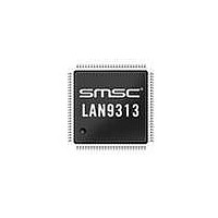
LAN9313I-NZW SMSC, LAN9313I-NZW Datasheet - Page 151

LAN9313I-NZW
Manufacturer Part Number
LAN9313I-NZW
Description
Ethernet ICs Three Port 10/100 Ethernet Switch
Manufacturer
SMSC
Type
Three Port Managed Ethernet Switchr
Datasheet
1.LAN9313-NZW.pdf
(399 pages)
Specifications of LAN9313I-NZW
Ethernet Connection Type
10 Base-T, 100 Base-TX
Minimum Operating Temperature
0 C
Mounting Style
SMD/SMT
Product
Ethernet Switches
Number Of Transceivers
1
Standard Supported
802.3, 802.3u
Data Rate
10 Mbps, 100 Mbps
Supply Voltage (max)
3.3 V
Supply Voltage (min)
0 V
Supply Current (max)
155 mA, 270 mA
Maximum Operating Temperature
+ 70 C
Package / Case
TQFP-100
Lead Free Status / RoHS Status
Lead free / RoHS Compliant
Available stocks
Company
Part Number
Manufacturer
Quantity
Price
Company:
Part Number:
LAN9313I-NZW
Manufacturer:
Standard
Quantity:
261
Company:
Part Number:
LAN9313I-NZW
Manufacturer:
Microchip Technology
Quantity:
10 000
- Current page: 151 of 399
- Download datasheet (5Mb)
Three Port 10/100 Managed Ethernet Switch with MII
Datasheet
SMSC LAN9313/LAN9313i
13.1.1
13.1.1.1
31:24
23:15
BITS
11:9
7:5
14
13
12
8
Interrupt De-assertion Interval (INT_DEAS)
This field determines the Interrupt Request De-assertion Interval in multiples
of 10 microseconds.
Setting this field to zero causes the device to disable the INT_DEAS Interval,
reset the interval counter and issue any pending interrupts. If a new, non-
zero value is written to this field, any subsequent interrupts will obey the new
setting.
RESERVED
Interrupt De-assertion Interval Clear (INT_DEAS_CLR)
Writing a 1 to this register clears the de-assertion counter in the Interrupt
Controller, thus causing a new de-assertion interval to begin (regardless of
whether or not the Interrupt Controller is currently in an active de-assertion
interval).
0: Normal operation
1: Clear de-assertion counter
Interrupt De-assertion Status (INT_DEAS_STS)
When set, this bit indicates that interrupts are currently in a de-assertion
interval, and will not be sent to the IRQ pin. When this bit is clear, interrupts
are not currently in a de-assertion interval, and will be sent to the IRQ pin.
0: No interrupts in de-assertion interval
1: Interrupts in de-assertion interval
Master Interrupt (IRQ_INT)
This read-only bit indicates the state of the internal IRQ line, regardless of
the setting of the IRQ_EN bit, or the state of the interrupt de-assertion
function. When this bit is set, one of the enabled interrupts is currently
active.
0: No enabled interrupts active
1: One or more enabled interrupts active
RESERVED
IRQ Enable (IRQ_EN)
This bit controls the final interrupt output to the IRQ pin. When clear, the IRQ
output is disabled and permanently de-asserted. This bit has no effect on
any internal interrupt status bits.
0: Disable output on IRQ pin
1: Enable output on IRQ pin
RESERVED
Interrupts
This section details the interrupt related System CSR’s. These registers control, configure, and monitor
the IRQ interrupt output pin and the various LAN9313/LAN9313i interrupt sources. For more
information on the LAN9313/LAN9313i interrupts, refer to
Interrupt Configuration Register (IRQ_CFG)
This read/write register configures and indicates the state of the IRQ signal.
Offset:
054h
DESCRIPTION
DATASHEET
151
Size:
Chapter 5, "System Interrupts," on page
32 bits
TYPE
R/W
R/W
R/W
RO
RO
RO
RO
RO
SC
SC
Revision 1.7 (06-29-10)
DEFAULT
00h
0h
0b
0b
0b
-
-
-
52.
Related parts for LAN9313I-NZW
Image
Part Number
Description
Manufacturer
Datasheet
Request
R

Part Number:
Description:
Three Port 10/100 Managed Ethernet Switch with MII
Manufacturer:
SMSC [SMSC Corporation]
Datasheet:

Part Number:
Description:
Ethernet ICs Three Port 10/100 Ethernet Switch
Manufacturer:
SMSC
Datasheet:

Part Number:
Description:
Ethernet ICs Three Port 10/100 Ethernet Switch
Manufacturer:
SMSC
Datasheet:

Part Number:
Description:
FAST ETHERNET PHYSICAL LAYER DEVICE
Manufacturer:
SMSC Corporation
Datasheet:

Part Number:
Description:
357-036-542-201 CARDEDGE 36POS DL .156 BLK LOPRO
Manufacturer:
SMSC Corporation
Datasheet:

Part Number:
Description:
357-036-542-201 CARDEDGE 36POS DL .156 BLK LOPRO
Manufacturer:
SMSC Corporation
Datasheet:

Part Number:
Description:
357-036-542-201 CARDEDGE 36POS DL .156 BLK LOPRO
Manufacturer:
SMSC Corporation
Datasheet:

Part Number:
Description:
4-PORT USB2.0 HUB CONTROLLER
Manufacturer:
SMSC Corporation
Datasheet:

Part Number:
Description:
Manufacturer:
SMSC Corporation
Datasheet:

Part Number:
Description:
Manufacturer:
SMSC Corporation
Datasheet:

Part Number:
Description:
FDC37C672ENHANCED SUPER I/O CONTROLLER WITH FAST IR
Manufacturer:
SMSC Corporation
Datasheet:

Part Number:
Description:
COM90C66LJPARCNET Controller/Transceiver with AT Interface and On-Chip RAM
Manufacturer:
SMSC Corporation
Datasheet:

Part Number:
Description:
Manufacturer:
SMSC Corporation
Datasheet:

Part Number:
Description:
Manufacturer:
SMSC Corporation
Datasheet:


