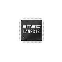
LAN9313I-NZW SMSC, LAN9313I-NZW Datasheet - Page 23

LAN9313I-NZW
Manufacturer Part Number
LAN9313I-NZW
Description
Ethernet ICs Three Port 10/100 Ethernet Switch
Manufacturer
SMSC
Type
Three Port Managed Ethernet Switchr
Datasheet
1.LAN9313-NZW.pdf
(399 pages)
Specifications of LAN9313I-NZW
Ethernet Connection Type
10 Base-T, 100 Base-TX
Minimum Operating Temperature
0 C
Mounting Style
SMD/SMT
Product
Ethernet Switches
Number Of Transceivers
1
Standard Supported
802.3, 802.3u
Data Rate
10 Mbps, 100 Mbps
Supply Voltage (max)
3.3 V
Supply Voltage (min)
0 V
Supply Current (max)
155 mA, 270 mA
Maximum Operating Temperature
+ 70 C
Package / Case
TQFP-100
Lead Free Status / RoHS Status
Lead free / RoHS Compliant
Available stocks
Company
Part Number
Manufacturer
Quantity
Price
Company:
Part Number:
LAN9313I-NZW
Manufacturer:
Standard
Quantity:
261
Company:
Part Number:
LAN9313I-NZW
Manufacturer:
Microchip Technology
Quantity:
10 000
- Current page: 23 of 399
- Download datasheet (5Mb)
Three Port 10/100 Managed Ethernet Switch with MII
Datasheet
SMSC LAN9313/LAN9313i
2.3
2.3.1
2.3.2
2.3.3
In addition, 8 of the GPIO pins can be alternatively configured as LED outputs. These pins, GPIO[7:0]
(nP1LED[3:0] and nP2LED[3:0]), may be enabled to drive Ethernet status LEDs for external indication
of various attributes of the switch ports.
The LAN9313/LAN9313i is designed to integrate into various embedded environments. To accomplish
compatibility with a wide range of applications, the LAN9313/LAN9313i can operate in 2 different
modes (MAC mode and PHY mode) and under various management conditions (unmanaged, SMI
managed, I
LAN9313/LAN9313i is determined by the MII_mode_strap and mngt_mode_strap[1:0] configuration
straps respectively. These modes and management types are detailed in the following sections.
Figure 2.2
the LAN9313/LAN9313i.
MAC Mode
The LAN9313/LAN9313i MAC mode utilizes an external PHY, which is connected to the MII pins, to
provide a third Ethernet network connection. In this mode, the LAN9313/LAN9313i acts as a MAC,
providing a communication path between the switch fabric and the external PHY. In MAC mode, the
LAN9313/LAN9313i may be unmanaged, SMI managed, I
Section 2.3.3, "Management
When an EEPROM is connected, the EEPROM loader can be used to load the initial device
configuration from the external EEPROM via the I
managed, the CPU can use the I
PHY Mode
The LAN9313/LAN9313i PHY mode utilizes an external MAC to provide a network path for the host
CPU. The external MII pins of the LAN9313/LAN9313i must be connected to an external MAC,
providing a communication path to the switch fabric. In PHY mode, the LAN9313/LAN9313i may be
unmanaged, SMI managed, I
Modes".
When an EEPROM is connected, the EEPROM loader can be used to load the initial device
configuration from the external EEPROM via the I
managed, the CPU can use the I
Management Modes
The LAN9313/LAN9313i provides various modes of management in both MAC and PHY modes of
operation. Two separate interfaces may be used to manage the LAN9313/LAN9313i: the I
interface or the SMI/MIIM(Media Independent Interface Management) slave interface.
The I
for an external CPU.
The SMI/MIIM interface runs as either an SMI/MIIM slave or MIIM master. The master mode is used
to access an external PHYs registers under CPU control (assuming the CPU is using I
slave mode is used for register access by the CPU or external MAC and provides access to either the
internal Port 1&2 PHY registers or to all non-PHY registers (using addresses 16-31 and a non-standard
extended address map). MIIM and SMI use the same pins and protocol and differ only in that SMI
provides access to all internal registers while MIIM provides access to only the Port 1&2 PHY registers.
A special mode provides access to the Virtual PHY, which mimics the register operation of a single
port standalone PHY. This is used for software compatibility during unmanaged operation.
The selection of LAN9313/LAN9313i modes is determined at startup via the MII_mode_strap and
mngt_mode_strap[1:0] configuration straps as detailed in
each mode of the LAN9313/LAN9313i are provided in
Modes of Operation
2
C/SPI interface runs as either an I
displays a typical system configuration for each mode and management type supported by
2
C managed, or SPI managed). The mode and management type of the
2
Modes".
C managed, or SPI managed as detailed in
2
2
C/Microwire interface to read or write the EEPROM.
C/Microwire interface to read or write the EEPROM.
DATASHEET
2
C slave or SPI slave and is used as a register access path
23
2
2
Figure
C/Microwire interface. Once operational, if
C/Microwire interface. Once operational, if
Table
2
C managed, or SPI managed as detailed in
2.2.
2.1. System configuration diagrams for
Section 2.3.3, "Management
Revision 1.7 (06-29-10)
2
C or SPI). The
2
C/SPI slave
Related parts for LAN9313I-NZW
Image
Part Number
Description
Manufacturer
Datasheet
Request
R

Part Number:
Description:
Three Port 10/100 Managed Ethernet Switch with MII
Manufacturer:
SMSC [SMSC Corporation]
Datasheet:

Part Number:
Description:
Ethernet ICs Three Port 10/100 Ethernet Switch
Manufacturer:
SMSC
Datasheet:

Part Number:
Description:
Ethernet ICs Three Port 10/100 Ethernet Switch
Manufacturer:
SMSC
Datasheet:

Part Number:
Description:
FAST ETHERNET PHYSICAL LAYER DEVICE
Manufacturer:
SMSC Corporation
Datasheet:

Part Number:
Description:
357-036-542-201 CARDEDGE 36POS DL .156 BLK LOPRO
Manufacturer:
SMSC Corporation
Datasheet:

Part Number:
Description:
357-036-542-201 CARDEDGE 36POS DL .156 BLK LOPRO
Manufacturer:
SMSC Corporation
Datasheet:

Part Number:
Description:
357-036-542-201 CARDEDGE 36POS DL .156 BLK LOPRO
Manufacturer:
SMSC Corporation
Datasheet:

Part Number:
Description:
4-PORT USB2.0 HUB CONTROLLER
Manufacturer:
SMSC Corporation
Datasheet:

Part Number:
Description:
Manufacturer:
SMSC Corporation
Datasheet:

Part Number:
Description:
Manufacturer:
SMSC Corporation
Datasheet:

Part Number:
Description:
FDC37C672ENHANCED SUPER I/O CONTROLLER WITH FAST IR
Manufacturer:
SMSC Corporation
Datasheet:

Part Number:
Description:
COM90C66LJPARCNET Controller/Transceiver with AT Interface and On-Chip RAM
Manufacturer:
SMSC Corporation
Datasheet:

Part Number:
Description:
Manufacturer:
SMSC Corporation
Datasheet:

Part Number:
Description:
Manufacturer:
SMSC Corporation
Datasheet:


