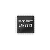
LAN9313I-NZW SMSC, LAN9313I-NZW Datasheet - Page 219

LAN9313I-NZW
Manufacturer Part Number
LAN9313I-NZW
Description
Ethernet ICs Three Port 10/100 Ethernet Switch
Manufacturer
SMSC
Type
Three Port Managed Ethernet Switchr
Datasheet
1.LAN9313-NZW.pdf
(399 pages)
Specifications of LAN9313I-NZW
Ethernet Connection Type
10 Base-T, 100 Base-TX
Minimum Operating Temperature
0 C
Mounting Style
SMD/SMT
Product
Ethernet Switches
Number Of Transceivers
1
Standard Supported
802.3, 802.3u
Data Rate
10 Mbps, 100 Mbps
Supply Voltage (max)
3.3 V
Supply Voltage (min)
0 V
Supply Current (max)
155 mA, 270 mA
Maximum Operating Temperature
+ 70 C
Package / Case
TQFP-100
Lead Free Status / RoHS Status
Lead free / RoHS Compliant
Available stocks
Company
Part Number
Manufacturer
Quantity
Price
Company:
Part Number:
LAN9313I-NZW
Manufacturer:
Standard
Quantity:
261
Company:
Part Number:
LAN9313I-NZW
Manufacturer:
Microchip Technology
Quantity:
10 000
- Current page: 219 of 399
- Download datasheet (5Mb)
Three Port 10/100 Managed Ethernet Switch with MII
Datasheet
SMSC LAN9313/LAN9313i
No Flow Control Enabled
Symmetric Pause
Asymmetric Pause Towards
Switch
Asymmetric Pause Towards MAC
BITS
4:0
7
6
5
100BASE-X Half Duplex
This bit indicates the emulated link partner PHY 100BASE-X half duplex
capability.
0: 100BASE-X half duplex ability not supported
1: 100BASE-X half duplex ability supported
10BASE-T Full Duplex
This bit indicates the emulated link partner PHY 10BASE-T full duplex
capability.
0: 10BASE-T full duplex ability not supported
1: 10BASE-T full duplex ability supported
10BASE-T Half Duplex
This bit indicates the emulated link partner PHY 10BASE-T half duplex
capability.
0: 10BASE-T half duplex ability not supported
1: 10BASE-T half duplex ability supported
Selector Field
This field identifies the type of message being sent by Auto-Negotiation.
00001: IEEE 802.3
Note 13.35 The reserved bits 31-16 are used to pad the register to 32-bits so that each register is on
Note 13.36 The emulated link partner does not support next page, always instantly sends its link code
Note 13.37 The emulated link partner’s asymmetric/symmetric pause ability is based upon the values
Note 13.38 The emulated link partner’s ability is based on the MII_DUPLEX pin, duplex_pol_strap_mii,
Table 13.5 Emulated Link Partner Pause Flow Control Ability Default Values
a DWORD boundary. When accessed serially (through the MII management protocol), the
register is 16-bits wide.
word, never sends a fault, and does not support 100BASE-T4.
of the
Advertisement Register
accommodates the request of the Virtual PHY, as shown in
"Virtual PHY Auto-Negotiation," on page 98
and speed_strap_mii, as well as on the Auto-Negotiation success.
default capabilities of the emulated link partner as a function of these signals. Configuration
strap values are latched upon the de-assertion of a chip-level reset as described in
4.2.4, "Configuration Straps," on page
negotiation, see
Asymmetric Pause
VPHY Symmetric
(register 4.10)
Pause
DESCRIPTION
0
1
0
1
Section 7.3.1, "Virtual PHY Auto-Negotiation," on page
DATASHEET
(VPHY_AN_ADV). Thus the emulated link partner always
VPHY Asymmetric
and
219
(register 4.11)
Pause
Pause
0
0
1
1
45. For more information on the Virtual PHY auto-
bits of the
for additional information.
Symmetric Pause
(register 5.10)
Link Partner
Virtual PHY Auto-Negotiation
0
1
1
0
Table
TYPE
13.5. See
RO
RO
RO
RO
Table 13.6
Revision 1.7 (06-29-10)
Asymmetric Pause
98.
(register 5.11)
Link Partner
Section 7.3.1,
Note 13.38
Note 13.38
Note 13.38
DEFAULT
00001b
defines the
0
0
1
1
Section
Related parts for LAN9313I-NZW
Image
Part Number
Description
Manufacturer
Datasheet
Request
R

Part Number:
Description:
Three Port 10/100 Managed Ethernet Switch with MII
Manufacturer:
SMSC [SMSC Corporation]
Datasheet:

Part Number:
Description:
Ethernet ICs Three Port 10/100 Ethernet Switch
Manufacturer:
SMSC
Datasheet:

Part Number:
Description:
Ethernet ICs Three Port 10/100 Ethernet Switch
Manufacturer:
SMSC
Datasheet:

Part Number:
Description:
FAST ETHERNET PHYSICAL LAYER DEVICE
Manufacturer:
SMSC Corporation
Datasheet:

Part Number:
Description:
357-036-542-201 CARDEDGE 36POS DL .156 BLK LOPRO
Manufacturer:
SMSC Corporation
Datasheet:

Part Number:
Description:
357-036-542-201 CARDEDGE 36POS DL .156 BLK LOPRO
Manufacturer:
SMSC Corporation
Datasheet:

Part Number:
Description:
357-036-542-201 CARDEDGE 36POS DL .156 BLK LOPRO
Manufacturer:
SMSC Corporation
Datasheet:

Part Number:
Description:
4-PORT USB2.0 HUB CONTROLLER
Manufacturer:
SMSC Corporation
Datasheet:

Part Number:
Description:
Manufacturer:
SMSC Corporation
Datasheet:

Part Number:
Description:
Manufacturer:
SMSC Corporation
Datasheet:

Part Number:
Description:
FDC37C672ENHANCED SUPER I/O CONTROLLER WITH FAST IR
Manufacturer:
SMSC Corporation
Datasheet:

Part Number:
Description:
COM90C66LJPARCNET Controller/Transceiver with AT Interface and On-Chip RAM
Manufacturer:
SMSC Corporation
Datasheet:

Part Number:
Description:
Manufacturer:
SMSC Corporation
Datasheet:

Part Number:
Description:
Manufacturer:
SMSC Corporation
Datasheet:


