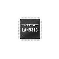
LAN9313I-NZW SMSC, LAN9313I-NZW Datasheet - Page 59

LAN9313I-NZW
Manufacturer Part Number
LAN9313I-NZW
Description
Ethernet ICs Three Port 10/100 Ethernet Switch
Manufacturer
SMSC
Type
Three Port Managed Ethernet Switchr
Datasheet
1.LAN9313-NZW.pdf
(399 pages)
Specifications of LAN9313I-NZW
Ethernet Connection Type
10 Base-T, 100 Base-TX
Minimum Operating Temperature
0 C
Mounting Style
SMD/SMT
Product
Ethernet Switches
Number Of Transceivers
1
Standard Supported
802.3, 802.3u
Data Rate
10 Mbps, 100 Mbps
Supply Voltage (max)
3.3 V
Supply Voltage (min)
0 V
Supply Current (max)
155 mA, 270 mA
Maximum Operating Temperature
+ 70 C
Package / Case
TQFP-100
Lead Free Status / RoHS Status
Lead free / RoHS Compliant
Available stocks
Company
Part Number
Manufacturer
Quantity
Price
Company:
Part Number:
LAN9313I-NZW
Manufacturer:
Standard
Quantity:
261
Company:
Part Number:
LAN9313I-NZW
Manufacturer:
Microchip Technology
Quantity:
10 000
- Current page: 59 of 399
- Download datasheet (5Mb)
Three Port 10/100 Managed Ethernet Switch with MII
Datasheet
SMSC LAN9313/LAN9313i
6.2.2
CSR_BUSY = 0
Switch Fabric CSR Reads
To perform a read of an individual switch fabric register, the read cycle must be initiated by performing
a single write to the
CSR_BUSY (bit 31) set, the CSR_ADDRESS field (bits 15:0) set to the desired register address, the
R_nW (bit 30) set, and the AUTO_INC and AUTO_DEC fields cleared. Valid data is available for
reading when the CSR_BUSY bit is cleared, indicating that the data can be read from the
CSR Interface Data Register
A second read method may be used which utilizes the auto increment/decrement function of the
Fabric CSR Interface Command Register (SWITCH_CSR_CMD)
addresses. When using this method, the
(SWITCH_CSR_CMD)
decrement(AUTO_DEC) bit set, the CSR_ADDRESS field written with the desired register address,
and the R_nW bit set. The completion of a read cycle is indicated by the clearing of the CSR_BUSY
bit, at which time the data can be read from the
(SWITCH_CSR_DATA). When the data is read, the address in the
Command Register (SWITCH_CSR_CMD)
read cycle is started automatically. The user should clear the AUTO_INC and AUTO_DEC bits before
reading the last data to avoid an unintended read cycle.
Figure 6.2
CSR Write
Write Data
Command
Command
illustrates the process required to perform a switch fabric CSR read.
Register
Register
Register
Read
Write
Idle
Figure 6.1 Switch Fabric CSR Write Access Flow Diagram
CSR_BUSY = 1
Switch Fabric CSR Interface Command Register (SWITCH_CSR_CMD)
must first be written with the auto increment(AUTO_INC) or auto
CSR_BUSY = 0
(SWITCH_CSR_DATA).
CSR Write Auto
DATASHEET
Increment /
Decrement
Command
Write Data
Command
Register
Register
Register
Write
Read
Idle
59
is incremented or decremented accordingly, and another
Switch Fabric CSR Interface Command Register
CSR_BUSY = 1
Switch Fabric CSR Interface Data Register
CSR_BUSY = 0
CSR Write Direct
Address
for reading sequential register
Command
Register
Register
Range
Switch Fabric CSR Interface
Direct
Write
Read
Data
Idle
CSR_BUSY = 1
Revision 1.7 (06-29-10)
Switch Fabric
Switch
with
Related parts for LAN9313I-NZW
Image
Part Number
Description
Manufacturer
Datasheet
Request
R

Part Number:
Description:
Three Port 10/100 Managed Ethernet Switch with MII
Manufacturer:
SMSC [SMSC Corporation]
Datasheet:

Part Number:
Description:
Ethernet ICs Three Port 10/100 Ethernet Switch
Manufacturer:
SMSC
Datasheet:

Part Number:
Description:
Ethernet ICs Three Port 10/100 Ethernet Switch
Manufacturer:
SMSC
Datasheet:

Part Number:
Description:
FAST ETHERNET PHYSICAL LAYER DEVICE
Manufacturer:
SMSC Corporation
Datasheet:

Part Number:
Description:
357-036-542-201 CARDEDGE 36POS DL .156 BLK LOPRO
Manufacturer:
SMSC Corporation
Datasheet:

Part Number:
Description:
357-036-542-201 CARDEDGE 36POS DL .156 BLK LOPRO
Manufacturer:
SMSC Corporation
Datasheet:

Part Number:
Description:
357-036-542-201 CARDEDGE 36POS DL .156 BLK LOPRO
Manufacturer:
SMSC Corporation
Datasheet:

Part Number:
Description:
4-PORT USB2.0 HUB CONTROLLER
Manufacturer:
SMSC Corporation
Datasheet:

Part Number:
Description:
Manufacturer:
SMSC Corporation
Datasheet:

Part Number:
Description:
Manufacturer:
SMSC Corporation
Datasheet:

Part Number:
Description:
FDC37C672ENHANCED SUPER I/O CONTROLLER WITH FAST IR
Manufacturer:
SMSC Corporation
Datasheet:

Part Number:
Description:
COM90C66LJPARCNET Controller/Transceiver with AT Interface and On-Chip RAM
Manufacturer:
SMSC Corporation
Datasheet:

Part Number:
Description:
Manufacturer:
SMSC Corporation
Datasheet:

Part Number:
Description:
Manufacturer:
SMSC Corporation
Datasheet:


