ADSP-3PARCBF548M01 Analog Devices Inc, ADSP-3PARCBF548M01 Datasheet - Page 74
ADSP-3PARCBF548M01
Manufacturer Part Number
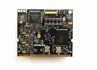
ADSP-3PARCBF548M01
Description
MODULE BOARD BF548
Manufacturer
Analog Devices Inc
Series
Blackfin®r
Specifications of ADSP-3PARCBF548M01
Module/board Type
Processor Module
For Use With/related Products
ADSP-BF548
Lead Free Status / RoHS Status
Lead free / RoHS Compliant


ADSP-BF542/ADSP-BF544/ADSP-BF547/ADSP-BF548/ADSP-BF549
ATA/ATAPI-6 Interface Timing
The following tables and figures specify ATAPI timing parame-
ters. For detailed parameter descriptions, refer to the ATAPI
specification (ANSI INCITS 361-2002).
include ATAPI timing parameter equations. System designers
should use these equations along with the parameters provided
Table 56. ATA/ATAPI-6 Timing Parameters
1
Table 57. ATA/ATAPI-6 System Timing Parameters
1
2
Parameter
t
t
t
t
t
t
Parameter
t
t
t
t
t
t
ATAPI output pins include ATAPI_CS0, ATAPI_CS1, A1-3, ATAPI_DIOR, ATAPI_DIOW, ATAPI_DMACK, ATAPI_D0-15, ATAPI_A0-2A, and ATAPI_D0-15A.
ATAPI output pins include ATAPI_CS0, ATAPI_CS1, A1-3, ATAPI_DIOR, ATAPI_DIOW, ATAPI_DMACK, ATAPI_D0-15, ATAPI_A0-2A, and ATAPI_D0-15A.
Output pin group A includes ATAPI_DIOR, ATAPI_DIOW, and ATAPI_DMACK. Output pin group B includes ATAPI_CS0, ATAPI_CS1, A1-3, ATAPI_D0-15,
SK1
OD
SUD
SUI
SUDU
HDU
SK2
BD
SK3
SK4
CDD
CDC
ATAPI_A0-2A, and ATAPI_D0-15A.
Difference in output delay after CLKOUT for ATAPI output pins
Output delay after CLKOUT for outputs
ATAPI_D0-15 or ATAPI_D0-15A Setup Before CLKOUT
ATAPI_IORDY Setup Before CLKOUT
ATAPI_D0-15 or ATAPI_D0-15A Setup Before ATAPI_IORDY (UDMA-in only)
ATAPI_D0-15 or ATAPI_D0-15A Hold After ATAPI_IORDY (UDMA-in only)
Maximum difference in board propagation delay between any 2 ATAPI output pins
Maximum board propagation delay.
Maximum difference in board propagation delay during a read between ATAPI_IORDY and ATAPI_D0-
15/ATAPI_D0-15A.
Maximum difference in ATAPI cable propagation delay between output pin group A and output pin
group B
ATAPI cable propagation delay for ATAPI_D0-15 and ATAPI_D0-15A signals.
ATAPI cable propagation delay for ATAPI_DIOR, ATAPI_DIOW, ATAPI_IORDY, and ATAPI_DMACK signals. ATAPI Cable Specification
2
Table 58
to
Rev. C | Page 74 of 100 | February 2010
1
Table 61
1
in
should be programmed such that ANSI INCITS 361-2002 speci-
fications are met for the desired transfer type and mode.
Table 56
and
Table
1
57. ATAPI timing control registers
Min
6
6
2
2.6
Source
System Design
System Design
System Design
ATAPI Cable Specification
ATAPI Cable Specification
Max
6
12
Unit
ns
ns
ns
ns
ns
ns
Related parts for ADSP-3PARCBF548M01
Image
Part Number
Description
Manufacturer
Datasheet
Request
R

Part Number:
Description:
±1.7g Dual-Axis IMEMS Accelerometer Evaluation Board
Manufacturer:
Analog Devices Inc
Datasheet:

Part Number:
Description:
Inertial Sensor Evaluation System
Manufacturer:
Analog Devices Inc
Datasheet:
Part Number:
Description:
Manufacturer:
Analog Devices Inc
Datasheet:
Part Number:
Description:
Manufacturer:
Analog Devices Inc
Datasheet:
Part Number:
Description:
Manufacturer:
Analog Devices Inc
Datasheet:
Part Number:
Description:
Manufacturer:
Analog Devices Inc
Datasheet:
Part Number:
Description:
Manufacturer:
Analog Devices Inc
Datasheet:
Part Number:
Description:
Manufacturer:
Analog Devices Inc
Datasheet:
Part Number:
Description:
Manufacturer:
Analog Devices Inc
Datasheet:
Part Number:
Description:
Manufacturer:
Analog Devices Inc
Datasheet:
Part Number:
Description:
Manufacturer:
Analog Devices Inc
Datasheet:
Part Number:
Description:
Manufacturer:
Analog Devices Inc
Datasheet:
Part Number:
Description:
Manufacturer:
Analog Devices Inc
Datasheet: