EVB9221-MINI SMSC, EVB9221-MINI Datasheet - Page 111
EVB9221-MINI
Manufacturer Part Number
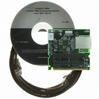
EVB9221-MINI
Description
EVALUATION BOARD LAN9221-ABZJ
Manufacturer
SMSC
Datasheet
1.LAN9221-ABZJ.pdf
(152 pages)
Specifications of EVB9221-MINI
Main Purpose
Interface, Ethernet Controller (PHY and MAC)
Embedded
No
Utilized Ic / Part
LAN9221
Primary Attributes
1 Port, 100BASE-TX/10BASE-T
Secondary Attributes
16-Bit, HP Auto-MDIX, Full and Half Duplex Support, 32-Bit CRC
Processor To Be Evaluated
LAN9221
Lead Free Status / RoHS Status
Lead free / RoHS Compliant
Other names
638-1074


High-Performance 16-bit Non-PCI 10/100 Ethernet Controller with Variable Voltage I/O
Datasheet
SMSC LAN9221/LAN9221i
5.4.3
BITS
31-0
EEPROM ADDRESS
Physical Address [31:0]. This field contains the lower 32 bits (31:0) of the Physical Address of the
LAN9221/LAN9221i device. The content of this field is undefined until loaded from the EEPROM at
power-on. The host can update the contents of this field after the initialization process has completed.
ADDRL—MAC Address Low Register
The MAC Address Low register contains the lower 32 bits of the physical address of the MAC. The
contents of this register are optionally loaded from the EEPROM at power-on through the EEPROM
Controller if a programmed EEPROM is detected. The least significant byte of this register (bits [7:0])
is loaded from address 0x01 of the EEPROM. The most significant byte of this register is loaded from
address 0x04 of the EEPROM. Please refer to
Table 5.7
reception of the Ethernet physical address. Also shown is the correlation between the EEPROM
addresses and ADDRL and ADDRH registers.
As an example, if the desired Ethernet physical address is 12-34-56-78-9A-BC, the ADDRL and
ADDRH registers would be programmed as shown in
load this configuration from the EEPROM are also shown.
Note: By convention, the left most byte of the Ethernet address (in this example 0x12) is the most
0x01
0x02
0x03
0x04
0x05
0x06
Offset:
Default Value:
significant byte and is transmitted/received first.
below illustrates the byte ordering of the ADDRL and ADDRH registers with respect to the
Figure 5.2 Example ADDRL, ADDRH and EEPROM Setup
Table 5.7 ADDRL, ADDRH and EEPROM Byte Ordering
31
31
0x78
xx
24
24
23
23
0x56
xx
ADDRH
ADDRL
16
16
3
FFFFFFFFh
15
15
ADDRL[23:16]
ADDRL[31:24]
ADDRH[15:8]
ADDRL[15:8]
ADDRH[7:0]
ADDRL[7:0]
0xBC
0x34
DATASHEET
ADDRN
8
8
111
DESCRIPTION
7
7
0x9A
0x12
Section 4.6
0
Attribute:
Size:
0
Figure
for more information on the EEPROM.
5.2. The values required to automatically
0x06
0x05
0x04
0x03
0x02
0x01
0x00
ORDER OF RECEPTION ON
EEPROM
R/W
32 bits
0xBC
0x9A
0xA5
0x78
0x56
0x34
0x12
ETHERNET
2
3
4
5
6
1
nd
rd
th
th
th
st
Revision 2.7 (03-15-10)
Related parts for EVB9221-MINI
Image
Part Number
Description
Manufacturer
Datasheet
Request
R


Part Number:
Description:
FAST ETHERNET PHYSICAL LAYER DEVICE
Manufacturer:
SMSC Corporation
Datasheet:
Part Number:
Description:
357-036-542-201 CARDEDGE 36POS DL .156 BLK LOPRO
Manufacturer:
SMSC Corporation
Datasheet:
Part Number:
Description:
357-036-542-201 CARDEDGE 36POS DL .156 BLK LOPRO
Manufacturer:
SMSC Corporation
Datasheet:
Part Number:
Description:
357-036-542-201 CARDEDGE 36POS DL .156 BLK LOPRO
Manufacturer:
SMSC Corporation
Datasheet:
Part Number:
Description:
4-PORT USB2.0 HUB CONTROLLER
Manufacturer:
SMSC Corporation
Datasheet:
Part Number:
Description:
Manufacturer:
SMSC Corporation
Datasheet:
Part Number:
Description:
Manufacturer:
SMSC Corporation
Datasheet:
Part Number:
Description:
FDC37C672ENHANCED SUPER I/O CONTROLLER WITH FAST IR
Manufacturer:
SMSC Corporation
Datasheet:
Part Number:
Description:
COM90C66LJPARCNET Controller/Transceiver with AT Interface and On-Chip RAM
Manufacturer:
SMSC Corporation
Datasheet:
Part Number:
Description:
Manufacturer:
SMSC Corporation
Datasheet:
Part Number:
Description:
Manufacturer:
SMSC Corporation
Datasheet:
Part Number:
Description:
Manufacturer:
SMSC Corporation
Datasheet:
Part Number:
Description:
Manufacturer:
SMSC Corporation
Datasheet: