EVB9221-MINI SMSC, EVB9221-MINI Datasheet - Page 136
EVB9221-MINI
Manufacturer Part Number
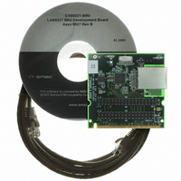
EVB9221-MINI
Description
EVALUATION BOARD LAN9221-ABZJ
Manufacturer
SMSC
Datasheet
1.LAN9221-ABZJ.pdf
(152 pages)
Specifications of EVB9221-MINI
Main Purpose
Interface, Ethernet Controller (PHY and MAC)
Embedded
No
Utilized Ic / Part
LAN9221
Primary Attributes
1 Port, 100BASE-TX/10BASE-T
Secondary Attributes
16-Bit, HP Auto-MDIX, Full and Half Duplex Support, 32-Bit CRC
Processor To Be Evaluated
LAN9221
Lead Free Status / RoHS Status
Lead free / RoHS Compliant
Other names
638-1074


Revision 2.7 (03-15-10)
6.8
SYMBOL
FIFO_SEL
nCS, nWR
Data Bus
t
cycle
t
t
t
t
t
t
csh
asu
dsu
A[2:1]
csl
ah
dh
In this mode the upper address inputs are not decoded, and any write to the LAN9221/LAN9221i will
write the TX Data FIFO. This mode is enabled when FIFO_SEL is driven high during a write access.
This is normally accomplished by connecting the FIFO_SEL signal to a high-order address line. This
mode is useful when the host processor must increment its address when accessing the
LAN9221/LAN9221i. Timing is identical to a PIO write, and the FIFO_SEL signal has the same timing
characteristics as the address lines.
Note: The “Data Bus” width is 16 bits.
Note: A TX Data FIFO Direct PIO Write cycle begins when both nCS and nWR are asserted. The
TX Data FIFO Direct PIO Writes
DESCRIPTION
Write Cycle Time
nCS, nWR Assertion Time
nCS, nWR Deassertion Time
Address, FIFO_SEL Setup to nCS, nWR Assertion
Address, FIFO_SEL Hold Time
Data Setup to nCS, nWR Deassertion
Data Hold Time
cycle ends when either or both nCS and nWR are deasserted. They may be asserted and
deasserted in any order.
Figure 6.7 TX Data FIFO Direct PIO Write Timing
Table 6.8 TX Data FIFO Direct PIO Write Timing
DATASHEET
136
High-Performance 16-bit Non-PCI 10/100 Ethernet Controller with Variable Voltage I/O
MIN
45
32
13
0
7
0
0
TYP
SMSC LAN9221/LAN9221i
MAX
Datasheet
UNITS
ns
ns
ns
ns
ns
ns
ns
Related parts for EVB9221-MINI
Image
Part Number
Description
Manufacturer
Datasheet
Request
R


Part Number:
Description:
FAST ETHERNET PHYSICAL LAYER DEVICE
Manufacturer:
SMSC Corporation
Datasheet:
Part Number:
Description:
357-036-542-201 CARDEDGE 36POS DL .156 BLK LOPRO
Manufacturer:
SMSC Corporation
Datasheet:
Part Number:
Description:
357-036-542-201 CARDEDGE 36POS DL .156 BLK LOPRO
Manufacturer:
SMSC Corporation
Datasheet:
Part Number:
Description:
357-036-542-201 CARDEDGE 36POS DL .156 BLK LOPRO
Manufacturer:
SMSC Corporation
Datasheet:
Part Number:
Description:
4-PORT USB2.0 HUB CONTROLLER
Manufacturer:
SMSC Corporation
Datasheet:
Part Number:
Description:
Manufacturer:
SMSC Corporation
Datasheet:
Part Number:
Description:
Manufacturer:
SMSC Corporation
Datasheet:
Part Number:
Description:
FDC37C672ENHANCED SUPER I/O CONTROLLER WITH FAST IR
Manufacturer:
SMSC Corporation
Datasheet:
Part Number:
Description:
COM90C66LJPARCNET Controller/Transceiver with AT Interface and On-Chip RAM
Manufacturer:
SMSC Corporation
Datasheet:
Part Number:
Description:
Manufacturer:
SMSC Corporation
Datasheet:
Part Number:
Description:
Manufacturer:
SMSC Corporation
Datasheet:
Part Number:
Description:
Manufacturer:
SMSC Corporation
Datasheet:
Part Number:
Description:
Manufacturer:
SMSC Corporation
Datasheet: