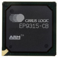
EP9315-CB Cirrus Logic Inc, EP9315-CB Datasheet - Page 410

EP9315-CB
Manufacturer Part Number
EP9315-CB
Description
IC ARM920T MCU 200MHZ 352-PBGA
Manufacturer
Cirrus Logic Inc
Series
EP9r
Specifications of EP9315-CB
Core Processor
ARM9
Core Size
16/32-Bit
Speed
200MHz
Connectivity
EBI/EMI, EIDE, Ethernet, I²C, IrDA, Keypad/Touchscreen, PCMCIA, SPI, UART/USART, USB
Peripherals
AC'97, DMA, I²:S, LCD, LED, MaverickKey, POR, PWM, WDT
Number Of I /o
16
Program Memory Type
ROMless
Ram Size
32K x 8
Voltage - Supply (vcc/vdd)
1.65 V ~ 3.6 V
Data Converters
A/D 8x12b
Oscillator Type
External
Operating Temperature
0°C ~ 70°C
Package / Case
352-BGA
Processor Series
EP93xx
Core
ARM920T
Data Bus Width
32 bit
3rd Party Development Tools
MDK-ARM, RL-ARM, ULINK2
Development Tools By Supplier
EDB9315A-Z
For Use With
598-1144 - KIT DEVELOPMENT EP9315 ARM9
Lead Free Status / RoHS Status
Contains lead / RoHS non-compliant
Eeprom Size
-
Program Memory Size
-
Lead Free Status / Rohs Status
No
Other names
598-1261
Available stocks
Company
Part Number
Manufacturer
Quantity
Price
Part Number:
EP9315-CBZ
Manufacturer:
CIRRUS
Quantity:
20 000
- Current page: 410 of 824
- Download datasheet (13Mb)
10
10-16
DMA Controller
EP93xx User’s Guide
10.1.10.5 Memory Block Transfer
10.1.10.6 Bandwidth Control
10.1.10.7 External DMA Request (DREQ) Mode
When the DONE interrupt is set, the processor can then write a one to clear the interrupt
before reprogramming the DMA to carry out another external DMA transfer. If the DEOT_TC
pin is configured as an output pin (TC), the DMA asserts TC when each buffers byte count
expires. It then rolls over to the other buffer. If the DEOT_TC pin is configured as an input pin
(DEOT), the DMA terminates transfers from the active buffer when DEOT is asserted and
rolls over to the other buffer. The DONE interrupt is not asserted when the DMA has another
buffer available to which it can roll over. However the NFB interrupt is generated when the
rollover occurs.
The DMA Controller M2M channels provide a feature whereby block moves of data from one
memory location can occur. If the CONTROL.SCT register bit is set for a channel, then its
source address will not increment. In order to use this feature, both the source and
destination addresses must be word-aligned, thus facilitating the transfer of a word of data
from 1 location to a block of memory with the number of destination memory addresses
written to is determined by the byte count register. For example, to copy a word to 10
consecutive destination addresses, then BCR must be set to 40.
The Bandwidth Control feature makes it possible to force the DMA off the AHB bus during
M2M transfers, to allow access to another device/peripheral. CONTROL.BWC register bits
provide 12 levels of block transfer sizes. If the BCR decrements to within 15 bytes of a
multiple of the decode of BWC, then the DMA bus request is negated until the bus cycle
terminates, to allow the AHB bus arbiter to switch masters.
If BWC is equal to zero, then the bus request stays asserted until BCR = zero, that is, the
transfer is finished. If the initial value of BCR is equal to the BWC decode, the bus request will
not be negated straight away. Some data must first be transferred.
When the external device requires DMA service, it asserts DREQ, which may be configured
as either edge or level sensitive using bit DREQP[1] of the CONTROL register.
External DMA requests are processed as follows:
• In level-sensitive mode, the external device requests service by asserting DREQ and
• For external devices that generate a pulsed signal for each transfer, edge-sensitive
leaving it asserted as long as it needs service. The DMA synchronizes the DREQ input
using 2 HCLK flip-flops for metastability protection. To prevent another transfer from
taking place, the external device must deassert the DREQ pin during the DACK (DMA
Acknowledge) cycle. The number of cycles that DACK is asserted is governed by the
number of wait states in the Static Memory Controller.
mode should be used. When the DMA detects a rising/falling edge on DREQ (as
configured by bit DREQP[0] of the CONTROL register), a request becomes pending.
The DMA synchronizes the latched DREQ input using 2 HCLK flip-flops for metastability
protection. The DREQS status bit is set to indicate that a request is pending.
Copyright 2007 Cirrus Logic
DS785UM1
Related parts for EP9315-CB
Image
Part Number
Description
Manufacturer
Datasheet
Request
R

Part Number:
Description:
IC ARM9 SOC ENH UNIV 352PBGA
Manufacturer:
Cirrus Logic Inc
Datasheet:

Part Number:
Description:
32-Bit Microcontroller IC
Manufacturer:
Cirrus Logic Inc
Datasheet:

Part Number:
Description:
IC ARM920T MCU 200MHZ 352-PBGA
Manufacturer:
Cirrus Logic Inc
Datasheet:

Part Number:
Description:
MCU, MPU & DSP Development Tools Eval Bd Uni. ARM9 SOC Processor
Manufacturer:
Cirrus Logic Inc
Datasheet:

Part Number:
Description:
IC ARM920T MCU 166MHZ 208-LQFP
Manufacturer:
Cirrus Logic Inc
Datasheet:

Part Number:
Description:
IC ARM920T MCU 200MHZ 352-PBGA
Manufacturer:
Cirrus Logic Inc
Datasheet:

Part Number:
Description:
IC ARM920T MCU 166MHZ 208-LQFP
Manufacturer:
Cirrus Logic Inc
Datasheet:

Part Number:
Description:
Development Kit
Manufacturer:
Cirrus Logic Inc
Datasheet:

Part Number:
Description:
Development Kit
Manufacturer:
Cirrus Logic Inc
Datasheet:

Part Number:
Description:
High-efficiency PFC + Fluorescent Lamp Driver Reference Design
Manufacturer:
Cirrus Logic Inc
Datasheet:

Part Number:
Description:
Development Kit
Manufacturer:
Cirrus Logic Inc
Datasheet:

Part Number:
Description:
Development Kit
Manufacturer:
Cirrus Logic Inc
Datasheet:

Part Number:
Description:
Development Kit
Manufacturer:
Cirrus Logic Inc
Datasheet:

Part Number:
Description:
Ref Bd For Speakerbar MSA & DSP Products
Manufacturer:
Cirrus Logic Inc


