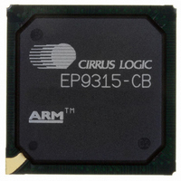
EP9315-CB Cirrus Logic Inc, EP9315-CB Datasheet - Page 523

EP9315-CB
Manufacturer Part Number
EP9315-CB
Description
IC ARM920T MCU 200MHZ 352-PBGA
Manufacturer
Cirrus Logic Inc
Series
EP9r
Specifications of EP9315-CB
Core Processor
ARM9
Core Size
16/32-Bit
Speed
200MHz
Connectivity
EBI/EMI, EIDE, Ethernet, I²C, IrDA, Keypad/Touchscreen, PCMCIA, SPI, UART/USART, USB
Peripherals
AC'97, DMA, I²:S, LCD, LED, MaverickKey, POR, PWM, WDT
Number Of I /o
16
Program Memory Type
ROMless
Ram Size
32K x 8
Voltage - Supply (vcc/vdd)
1.65 V ~ 3.6 V
Data Converters
A/D 8x12b
Oscillator Type
External
Operating Temperature
0°C ~ 70°C
Package / Case
352-BGA
Processor Series
EP93xx
Core
ARM920T
Data Bus Width
32 bit
3rd Party Development Tools
MDK-ARM, RL-ARM, ULINK2
Development Tools By Supplier
EDB9315A-Z
For Use With
598-1144 - KIT DEVELOPMENT EP9315 ARM9
Lead Free Status / RoHS Status
Contains lead / RoHS non-compliant
Eeprom Size
-
Program Memory Size
-
Lead Free Status / Rohs Status
No
Other names
598-1261
Available stocks
Company
Part Number
Manufacturer
Quantity
Price
Part Number:
EP9315-CBZ
Manufacturer:
CIRRUS
Quantity:
20 000
- Current page: 523 of 824
- Download datasheet (13Mb)
DS785UM1
14.1 Introduction
14.2 UART Overview
UART1 is the collection of a UART block along with a block to support a 9 pin modem
interface and a block to support synchronous and asynchronous HDLC protocol support for
full duplex transmit and receive. The following sections address each of these blocks.
Transmit and Receive data transfers through UART1 can either be managed by the DMA,
interrupt driven, or CPU polled operations. A loopback control bit is available to enable
system testing by routing the transmit data stream into the receiver.
The UART performs:
The CPU reads and writes data and control/status information via the AMBA APB interface.
The transmit and receive paths are buffered with internal FIFO memories allowing up to
16 bytes to be stored independently in both transmit and receive modes.
The UART:
The UART operation and baud rate values are controlled by the line control register
(UART1LinCtrl).
The UART can generate:
If a framing, parity or break error occurs during reception, the appropriate error bit is set, and
is stored in the FIFO. If an overrun condition occurs, the overrun register bit is set
immediately and FIFO data is prevented from being overwritten.
• Serial-to-parallel conversion on data received from a peripheral device.
• Parallel-to-serial conversion on data transmitted to the peripheral device.
• Includes a programmable baud rate generator which generates a common transmit and
• Offers similar functionality to the industry-standard 16C550 UART device.
• Supports baud rates of up to 115.2 Kbps and beyond, subject to UARTCLK reference
• Four individually-maskable interrupts from the receive, transmit and modem status logic
• A single combined interrupt so that the output is asserted if any of the individual
receive internal clock from the UART internal reference clock input, UARTCLK.
clock frequency.
blocks.
interrupts are asserted and unmasked.
14UART1 With HDLC and Modem Control Signals
Copyright 2007 Cirrus Logic
Chapter 14
14-1
14
Related parts for EP9315-CB
Image
Part Number
Description
Manufacturer
Datasheet
Request
R

Part Number:
Description:
IC ARM9 SOC ENH UNIV 352PBGA
Manufacturer:
Cirrus Logic Inc
Datasheet:

Part Number:
Description:
32-Bit Microcontroller IC
Manufacturer:
Cirrus Logic Inc
Datasheet:

Part Number:
Description:
IC ARM920T MCU 200MHZ 352-PBGA
Manufacturer:
Cirrus Logic Inc
Datasheet:

Part Number:
Description:
MCU, MPU & DSP Development Tools Eval Bd Uni. ARM9 SOC Processor
Manufacturer:
Cirrus Logic Inc
Datasheet:

Part Number:
Description:
IC ARM920T MCU 166MHZ 208-LQFP
Manufacturer:
Cirrus Logic Inc
Datasheet:

Part Number:
Description:
IC ARM920T MCU 200MHZ 352-PBGA
Manufacturer:
Cirrus Logic Inc
Datasheet:

Part Number:
Description:
IC ARM920T MCU 166MHZ 208-LQFP
Manufacturer:
Cirrus Logic Inc
Datasheet:

Part Number:
Description:
Development Kit
Manufacturer:
Cirrus Logic Inc
Datasheet:

Part Number:
Description:
Development Kit
Manufacturer:
Cirrus Logic Inc
Datasheet:

Part Number:
Description:
High-efficiency PFC + Fluorescent Lamp Driver Reference Design
Manufacturer:
Cirrus Logic Inc
Datasheet:

Part Number:
Description:
Development Kit
Manufacturer:
Cirrus Logic Inc
Datasheet:

Part Number:
Description:
Development Kit
Manufacturer:
Cirrus Logic Inc
Datasheet:

Part Number:
Description:
Development Kit
Manufacturer:
Cirrus Logic Inc
Datasheet:

Part Number:
Description:
Ref Bd For Speakerbar MSA & DSP Products
Manufacturer:
Cirrus Logic Inc


