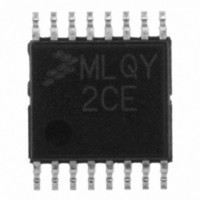
MCL908QY2CDTE Freescale Semiconductor, MCL908QY2CDTE Datasheet - Page 112

MCL908QY2CDTE
Manufacturer Part Number
MCL908QY2CDTE
Description
IC MCU 8BIT 1.5K FLASH 16-TSSOP
Manufacturer
Freescale Semiconductor
Series
HC08r
Datasheet
1.MCL908QY2CDWE.pdf
(182 pages)
Specifications of MCL908QY2CDTE
Core Processor
HC08
Core Size
8-Bit
Speed
2MHz
Peripherals
LVD, POR, PWM
Number Of I /o
13
Program Memory Size
1.5KB (1.5K x 8)
Program Memory Type
FLASH
Ram Size
128 x 8
Voltage - Supply (vcc/vdd)
2.4 V ~ 3.6 V
Data Converters
A/D 4x8b
Oscillator Type
Internal
Operating Temperature
-40°C ~ 85°C
Package / Case
16-TSSOP
Lead Free Status / RoHS Status
Lead free / RoHS Compliant
Eeprom Size
-
Connectivity
-
- Current page: 112 of 182
- Download datasheet (2Mb)
System Integration Module (SIM)
The LDA opcode is prefetched by both the INT1 and INT2 return-from-interrupt (RTI) instructions.
However, in the case of the INT1 RTI prefetch, this is a redundant operation.
13.6.1.2 SWI Instruction
The SWI instruction is a non-maskable instruction that causes an interrupt regardless of the state of the
interrupt mask (I bit) in the condition code register.
13.6.2 Interrupt Status Registers
The flags in the interrupt status registers identify maskable interrupt sources.
interrupt sources and the interrupt status register flags that they set. The interrupt status registers can be
useful for debugging.
13.6.2.1 Interrupt Status Register 1
112
Priority
Highest
Lowest
1. The I bit in the condition code register is a global mask for all interrupt sources except the SWI
Address: $FE04
To maintain compatibility with the M6805 Family, the H register is not
pushed on the stack during interrupt entry. If the interrupt service routine
modifies the H register or uses the indexed addressing mode, software
should save the H register and then restore it prior to exiting the routine.
A software interrupt pushes PC onto the stack. A software interrupt does
not push PC – 1, as a hardware interrupt does.
instruction.
Reset:
Read:
Write:
Reset
SWI instruction
IRQ pin
Timer channel 0 interrupt
Timer channel 1 interrupt
Timer overflow interrupt
Keyboard interrupt
ADC conversion complete interrupt
Bit 7
R
R
0
0
Figure 13-11. Interrupt Status Register 1 (INT1)
= Reserved
MC68HLC908QY/QT Family Data Sheet, Rev. 3
Source
IF5
R
6
0
Table 13-3. Interrupt Sources
IF4
R
5
0
NOTE
NOTE
IF3
R
4
0
COCO
CH0F
CH1F
KEYF
IRQF
Flag
TOF
—
—
IMASKK
R
3
0
0
Mask
IMASK
CH0IE
CH1IE
AIEN
TOIE
—
—
(1)
IF1
Register
R
2
0
Flag
IF15
IF14
INT
IF1
IF3
IF4
IF5
—
—
Table 13-3
R
1
0
0
$FFDE–$FFDF
$FFFC–$FFFD
$FFFE–$FFFF
$FFFA–$FFFB
$FFF6–$FFF7
$FFF4–$FFF5
$FFF2–$FFF3
$FFE0–$FFE1
Address
Vector
Freescale Semiconductor
Bit 0
R
0
0
summarizes the
Related parts for MCL908QY2CDTE
Image
Part Number
Description
Manufacturer
Datasheet
Request
R
Part Number:
Description:
Manufacturer:
Freescale Semiconductor, Inc
Datasheet:
Part Number:
Description:
Manufacturer:
Freescale Semiconductor, Inc
Datasheet:
Part Number:
Description:
Manufacturer:
Freescale Semiconductor, Inc
Datasheet:
Part Number:
Description:
Manufacturer:
Freescale Semiconductor, Inc
Datasheet:
Part Number:
Description:
Manufacturer:
Freescale Semiconductor, Inc
Datasheet:
Part Number:
Description:
Manufacturer:
Freescale Semiconductor, Inc
Datasheet:
Part Number:
Description:
Manufacturer:
Freescale Semiconductor, Inc
Datasheet:
Part Number:
Description:
Manufacturer:
Freescale Semiconductor, Inc
Datasheet:
Part Number:
Description:
Manufacturer:
Freescale Semiconductor, Inc
Datasheet:
Part Number:
Description:
Manufacturer:
Freescale Semiconductor, Inc
Datasheet:
Part Number:
Description:
Manufacturer:
Freescale Semiconductor, Inc
Datasheet:
Part Number:
Description:
Manufacturer:
Freescale Semiconductor, Inc
Datasheet:
Part Number:
Description:
Manufacturer:
Freescale Semiconductor, Inc
Datasheet:
Part Number:
Description:
Manufacturer:
Freescale Semiconductor, Inc
Datasheet:
Part Number:
Description:
Manufacturer:
Freescale Semiconductor, Inc
Datasheet:


