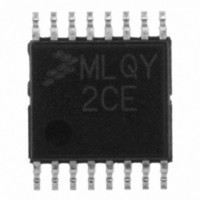
MCL908QY2CDTE Freescale Semiconductor, MCL908QY2CDTE Datasheet - Page 137

MCL908QY2CDTE
Manufacturer Part Number
MCL908QY2CDTE
Description
IC MCU 8BIT 1.5K FLASH 16-TSSOP
Manufacturer
Freescale Semiconductor
Series
HC08r
Datasheet
1.MCL908QY2CDWE.pdf
(182 pages)
Specifications of MCL908QY2CDTE
Core Processor
HC08
Core Size
8-Bit
Speed
2MHz
Peripherals
LVD, POR, PWM
Number Of I /o
13
Program Memory Size
1.5KB (1.5K x 8)
Program Memory Type
FLASH
Ram Size
128 x 8
Voltage - Supply (vcc/vdd)
2.4 V ~ 3.6 V
Data Converters
A/D 4x8b
Oscillator Type
Internal
Operating Temperature
-40°C ~ 85°C
Package / Case
16-TSSOP
Lead Free Status / RoHS Status
Lead free / RoHS Compliant
Eeprom Size
-
Connectivity
-
- Current page: 137 of 182
- Download datasheet (2Mb)
When the internal address bus matches the value written in the break address registers or when software
writes a 1 to the BRKA bit in the break status and control register, the CPU starts a break interrupt by:
The break interrupt timing is:
By updating a break address and clearing the BRKA bit in a break interrupt routine, a break interrupt can
be generated continuously.
A break address should be placed at the address of the instruction opcode. When software does not
change the break address and clears the BRKA bit in the first break interrupt routine, the next break
interrupt will not be generated after exiting the interrupt routine even when the internal address bus
matches the value written in the break address registers.
15.2.1.1 Flag Protection During Break Interrupts
The system integration module (SIM) controls whether or not module status bits can be cleared during
the break state. The BCFE bit in the break flag control register (BFCR) enables software to clear status
bits during the break state. See
for each module.
15.2.1.2 TIM During Break Interrupts
A break interrupt stops the timer counter.
15.2.1.3 COP During Break Interrupts
The COP is disabled during a break interrupt with monitor mode when BDCOP bit is set in break auxiliary
register (BRKAR).
15.2.2 Break Module Registers
These registers control and monitor operation of the break module:
Freescale Semiconductor
•
•
•
•
•
•
•
•
•
•
Loading the instruction register with the SWI instruction
Loading the program counter with $FFFC and $FFFD ($FEFC and $FEFD in monitor mode)
When a break address is placed at the address of the instruction opcode, the instruction is not
executed until after completion of the break interrupt routine.
When a break address is placed at an address of an instruction operand, the instruction is executed
before the break interrupt.
When software writes a 1 to the BRKA bit, the break interrupt occurs just before the next instruction
is executed.
Break status and control register (BRKSCR)
Break address register high (BRKH)
Break address register low (BRKL)
Break status register (BSR)
Break flag control register (BFCR)
13.8.2 Break Flag Control Register
MC68HLC908QY/QT Family Data Sheet, Rev. 3
CAUTION
and the Break Interrupts subsection
Break Module (BRK)
137
Related parts for MCL908QY2CDTE
Image
Part Number
Description
Manufacturer
Datasheet
Request
R
Part Number:
Description:
Manufacturer:
Freescale Semiconductor, Inc
Datasheet:
Part Number:
Description:
Manufacturer:
Freescale Semiconductor, Inc
Datasheet:
Part Number:
Description:
Manufacturer:
Freescale Semiconductor, Inc
Datasheet:
Part Number:
Description:
Manufacturer:
Freescale Semiconductor, Inc
Datasheet:
Part Number:
Description:
Manufacturer:
Freescale Semiconductor, Inc
Datasheet:
Part Number:
Description:
Manufacturer:
Freescale Semiconductor, Inc
Datasheet:
Part Number:
Description:
Manufacturer:
Freescale Semiconductor, Inc
Datasheet:
Part Number:
Description:
Manufacturer:
Freescale Semiconductor, Inc
Datasheet:
Part Number:
Description:
Manufacturer:
Freescale Semiconductor, Inc
Datasheet:
Part Number:
Description:
Manufacturer:
Freescale Semiconductor, Inc
Datasheet:
Part Number:
Description:
Manufacturer:
Freescale Semiconductor, Inc
Datasheet:
Part Number:
Description:
Manufacturer:
Freescale Semiconductor, Inc
Datasheet:
Part Number:
Description:
Manufacturer:
Freescale Semiconductor, Inc
Datasheet:
Part Number:
Description:
Manufacturer:
Freescale Semiconductor, Inc
Datasheet:
Part Number:
Description:
Manufacturer:
Freescale Semiconductor, Inc
Datasheet:


