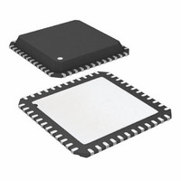
ATA6603P-PLQW Atmel, ATA6603P-PLQW Datasheet - Page 213

ATA6603P-PLQW
Manufacturer Part Number
ATA6603P-PLQW
Description
MCU W/LIN TXRX REG WTCHDG 48-QFN
Manufacturer
Atmel
Series
AVR® ATA66 LIN-SBCr
Datasheet
1.ATA6603P-PLQW.pdf
(360 pages)
Specifications of ATA6603P-PLQW
Core Processor
AVR
Core Size
8-Bit
Speed
16MHz
Connectivity
I²C, LIN, SPI, UART/USART
Peripherals
Brown-out Detect/Reset, POR, PWM, WDT
Number Of I /o
23
Program Memory Size
16KB (16K x 8)
Program Memory Type
FLASH
Eeprom Size
512 x 8
Ram Size
1K x 8
Voltage - Supply (vcc/vdd)
2.7 V ~ 5.5 V
Data Converters
A/D 8x10b
Oscillator Type
Internal
Operating Temperature
-40°C ~ 125°C
Package / Case
48-QFN Exposed Pad
Lead Free Status / RoHS Status
Lead free / RoHS Compliant
Available stocks
Company
Part Number
Manufacturer
Quantity
Price
Company:
Part Number:
ATA6603P-PLQW
Manufacturer:
ATMEL
Quantity:
2 000
Part Number:
ATA6603P-PLQW
Manufacturer:
ATMEL/爱特梅尔
Quantity:
20 000
- Current page: 213 of 360
- Download datasheet (6Mb)
4.17.9.4
4921E–AUTO–09/09
USART Control and Status Register n C – UCSRnC
Table 4-74.
Note:
Table 4-75.
Initial Value
Read/Write
• Bit 2 – UCSZn2: Character Size n
• Bit 1 – RXB8n: Receive Data Bit 8 n
• Bit 0 – TXB8n: Transmit Data Bit 8 n
• Bits 7:6 – UMSELn1:0 USART Mode Select
• Bits 5:4 – UPMn1:0: Parity Mode
• Bit 3 – USBSn: Stop Bit Select
The UCSZn2 bits combined with the UCSZn1:0 bit in UCSRnC sets the number of data bits
(Character SiZe) in a frame the Receiver and Transmitter use.
RXB8n is the ninth data bit of the received character when operating with serial frames with
nine data bits. Must be read before reading the low bits from UDRn.
TXB8n is the ninth data bit in the character to be transmitted when operating with serial
frames with nine data bits. Must be written before writing the low bits to UDRn.
These bits select the mode of operation of the USARTn as shown in
These bits enable and set type of parity generation and check. If enabled, the Transmitter
will automatically generate and send the parity of the transmitted data bits within each
frame. The Receiver will generate a parity value for the incoming data and compare it to the
UPMn setting. If a mismatch is detected, the UPEn Flag in UCSRnA will be set.
This bit selects the number of stop bits to be inserted by the Transmitter. The Receiver
ignores this setting.
Bit
UMSELn1
UPMn1
1. See
0
0
1
1
0
0
1
1
operation
UMSELn1
UMSELn Bits Settings
UPMn Bits Settings
R/W
“USART in SPI Mode” on page 218
7
0
UMSELn0
R/W
6
0
UMSELn0
UPMn0
0
1
0
1
0
1
0
1
UPMn1
R/W
5
0
UPMn0
Parity Mode
Disabled
Reserved
Enabled, Even Parity
Enabled, Odd Parity
Mode
Asynchronous USART
Synchronous USART
(Reserved)
Master SPI (MSPIM)
R/W
4
0
for full description of the Master SPI Mode (MSPIM)
USBSn
R/W
3
0
UCSZn1
ATA6602/ATA6603
R/W
(1)
2
1
UCSZn0
R/W
1
1
Table
UCPOLn
4-74.
R/W
0
0
UCSRnC
213
Related parts for ATA6603P-PLQW
Image
Part Number
Description
Manufacturer
Datasheet
Request
R

Part Number:
Description:
MCU, MPU & DSP Development Tools Demoboard LIN-MCM
Manufacturer:
Atmel
Datasheet:

Part Number:
Description:
Microcontroller With Lin Transceiver, 5v Regulator And Watchdog
Manufacturer:
ATMEL Corporation
Datasheet:

Part Number:
Description:
DEV KIT FOR AVR/AVR32
Manufacturer:
Atmel
Datasheet:

Part Number:
Description:
INTERVAL AND WIPE/WASH WIPER CONTROL IC WITH DELAY
Manufacturer:
ATMEL Corporation
Datasheet:

Part Number:
Description:
Low-Voltage Voice-Switched IC for Hands-Free Operation
Manufacturer:
ATMEL Corporation
Datasheet:

Part Number:
Description:
MONOLITHIC INTEGRATED FEATUREPHONE CIRCUIT
Manufacturer:
ATMEL Corporation
Datasheet:

Part Number:
Description:
AM-FM Receiver IC U4255BM-M
Manufacturer:
ATMEL Corporation
Datasheet:

Part Number:
Description:
Monolithic Integrated Feature Phone Circuit
Manufacturer:
ATMEL Corporation
Datasheet:

Part Number:
Description:
Multistandard Video-IF and Quasi Parallel Sound Processing
Manufacturer:
ATMEL Corporation
Datasheet:

Part Number:
Description:
High-performance EE PLD
Manufacturer:
ATMEL Corporation
Datasheet:

Part Number:
Description:
8-bit Flash Microcontroller
Manufacturer:
ATMEL Corporation
Datasheet:

Part Number:
Description:
2-Wire Serial EEPROM
Manufacturer:
ATMEL Corporation
Datasheet:


