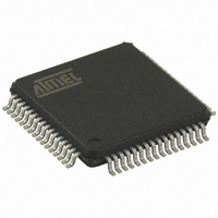
AT32UC3B0512-A2UT Atmel, AT32UC3B0512-A2UT Datasheet - Page 241

AT32UC3B0512-A2UT
Manufacturer Part Number
AT32UC3B0512-A2UT
Description
IC MCU AVR32 512K FLASH 64TQFP
Manufacturer
Atmel
Series
AVR®32 UC3r
Specifications of AT32UC3B0512-A2UT
Core Processor
AVR
Core Size
32-Bit
Speed
60MHz
Connectivity
I²C, IrDA, SPI, SSC, UART/USART, USB
Peripherals
Brown-out Detect/Reset, DMA, POR, PWM, WDT
Number Of I /o
44
Program Memory Size
512KB (512K x 8)
Program Memory Type
FLASH
Ram Size
96K x 8
Voltage - Supply (vcc/vdd)
1.65 V ~ 1.95 V
Data Converters
A/D 8x10b
Oscillator Type
Internal
Operating Temperature
-40°C ~ 85°C
Package / Case
64-TQFP, 64-VQFP
Controller Family/series
AT32UC3B
No. Of I/o's
44
Ram Memory Size
96KB
Cpu Speed
60MHz
No. Of Timers
1
Rohs Compliant
Yes
Lead Free Status / RoHS Status
Lead free / RoHS Compliant
Eeprom Size
-
Available stocks
Company
Part Number
Manufacturer
Quantity
Price
Company:
Part Number:
AT32UC3B0512-A2UT
Manufacturer:
MURATA
Quantity:
11 450
Part Number:
AT32UC3B0512-A2UT
Manufacturer:
ATMEL/爱特梅尔
Quantity:
20 000
- Current page: 241 of 692
- Download datasheet (11Mb)
19.13.6
19.13.6.1
Figure 19-27. Clock Synchronization in Read Mode
Notes:
32059K–03/2011
TWI_THR
TXCOMP
SVREAD
SCLWS
SVACC
TXRDY
TWCK
1. TXRDY is reset when data has been written in the TH to the shift register and set when this data has been acknowledged or
2. At the end of the read sequence, TXCOMP is set after a STOP or after a REPEATED_START + an address different from
3. SCLWS is automatically set when the clock synchronization mechanism is started.
Clock Synchronization
non acknowledged.
SADR.
Clock Synchronization in Read Mode
1
2
S
S
The data is memorized in TWI_THR until a new value is written
TWI_THR is transmitted to the shift register
The clock is stretched after the ACK, the state of TWD is undefined during clock stretching
As soon as a START is detected
SADR
In both read and write modes, it may happen that THR/RHR buffer is not filled /emptied before
the emission/reception of a new character. In this case, to avoid sending/receiving undesired
data, a clock stretching mechanism is implemented.
The clock is tied low if the shift register is empty and if a STOP or REPEATED START condition
was not detected. It is tied low until the shift register is loaded.
Figure 19-27 on page 241
DATA0
DATA0
R
Write THR
A
1
DATA0
A
describes the clock synchronization in Read mode.
DATA1
DATA1
CLOCK is tied low by the TWI
as long as THR is empty
A
XXXXXXX
2
DATA2
DATA2
Ack or Nack from the master
NA
AT32UC3B
S
241
Related parts for AT32UC3B0512-A2UT
Image
Part Number
Description
Manufacturer
Datasheet
Request
R

Part Number:
Description:
DEV KIT FOR AVR/AVR32
Manufacturer:
Atmel
Datasheet:

Part Number:
Description:
INTERVAL AND WIPE/WASH WIPER CONTROL IC WITH DELAY
Manufacturer:
ATMEL Corporation
Datasheet:

Part Number:
Description:
Low-Voltage Voice-Switched IC for Hands-Free Operation
Manufacturer:
ATMEL Corporation
Datasheet:

Part Number:
Description:
MONOLITHIC INTEGRATED FEATUREPHONE CIRCUIT
Manufacturer:
ATMEL Corporation
Datasheet:

Part Number:
Description:
AM-FM Receiver IC U4255BM-M
Manufacturer:
ATMEL Corporation
Datasheet:

Part Number:
Description:
Monolithic Integrated Feature Phone Circuit
Manufacturer:
ATMEL Corporation
Datasheet:

Part Number:
Description:
Multistandard Video-IF and Quasi Parallel Sound Processing
Manufacturer:
ATMEL Corporation
Datasheet:

Part Number:
Description:
High-performance EE PLD
Manufacturer:
ATMEL Corporation
Datasheet:

Part Number:
Description:
8-bit Flash Microcontroller
Manufacturer:
ATMEL Corporation
Datasheet:

Part Number:
Description:
2-Wire Serial EEPROM
Manufacturer:
ATMEL Corporation
Datasheet:


