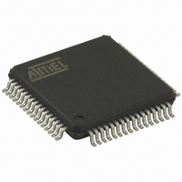
AT32UC3B0512-A2UT Atmel, AT32UC3B0512-A2UT Datasheet - Page 252

AT32UC3B0512-A2UT
Manufacturer Part Number
AT32UC3B0512-A2UT
Description
IC MCU AVR32 512K FLASH 64TQFP
Manufacturer
Atmel
Series
AVR®32 UC3r
Specifications of AT32UC3B0512-A2UT
Core Processor
AVR
Core Size
32-Bit
Speed
60MHz
Connectivity
I²C, IrDA, SPI, SSC, UART/USART, USB
Peripherals
Brown-out Detect/Reset, DMA, POR, PWM, WDT
Number Of I /o
44
Program Memory Size
512KB (512K x 8)
Program Memory Type
FLASH
Ram Size
96K x 8
Voltage - Supply (vcc/vdd)
1.65 V ~ 1.95 V
Data Converters
A/D 8x10b
Oscillator Type
Internal
Operating Temperature
-40°C ~ 85°C
Package / Case
64-TQFP, 64-VQFP
Controller Family/series
AT32UC3B
No. Of I/o's
44
Ram Memory Size
96KB
Cpu Speed
60MHz
No. Of Timers
1
Rohs Compliant
Yes
Lead Free Status / RoHS Status
Lead free / RoHS Compliant
Eeprom Size
-
Available stocks
Company
Part Number
Manufacturer
Quantity
Price
Company:
Part Number:
AT32UC3B0512-A2UT
Manufacturer:
MURATA
Quantity:
11 450
Part Number:
AT32UC3B0512-A2UT
Manufacturer:
ATMEL/爱特梅尔
Quantity:
20 000
- Current page: 252 of 692
- Download datasheet (11Mb)
19.14.6
Name:
Access:
Offset:
Reset Value: 0x0000F009
• EOSACC: End Of Slave Access (clear on read)
• SCLWS: Clock Wait State (automatically set / reset)
• ARBLST: Arbitration Lost (clear on read)
• NACK: Not Acknowledged (clear on read)
• OVRE: Overrun Error (clear on read)
• GACC: General Call Access (clear on read)
32059K–03/2011
31
23
15
–
–
–
7
–
This bit is only used in Slave mode.
0 = A slave access is being performing.
1 = The Slave Access is finished. End Of Slave Access is automatically set as soon as SVACC is reset.
EOSACC behavior can be seen in
This bit is only used in Slave mode.
0 = The clock is not stretched.
1 = The clock is stretched. THR / RHR buffer is not filled / emptied before the emission / reception of a new character.
SCLWS behavior can be seen in
This bit is only used in Master mode.
0 = Arbitration won.
1 = Arbitration lost. Another master of the TWI bus has won the multi-master arbitration. TXCOMP is set at the same time.
NACK used in Master mode:
0 = Each data byte has been correctly received by the far-end side TWI slave component.
1 = A data byte has not been acknowledged by the slave component. Set at the same time as TXCOMP.
NACK used in Slave Read mode:
0 = Each data byte has been correctly received by the Master.
1 = In read mode, a data byte has not been acknowledged by the Master. When NACK is set the programmer must not fill THR
even if TXRDY is set, because it means that the Master will stop the data transfer or re initiate it.
Note that in Slave Write mode all data are acknowledged by the TWI.
This bit is only used in Slave mode.
0 = RHR has not been loaded while RXRDY was set
1 = RHR has been loaded while RXRDY was set. Reset by read in SR when TXCOMP is set.
This bit is only used in Slave mode.
0 = No General Call has been detected.
Status Register
SR
Read-only
0x20
OVRE
30
22
14
–
–
–
6
GACC
29
21
13
–
–
–
5
Figure 19-27 on page 241
Figure 19-29 on page 243
SVACC
28
20
12
–
–
–
4
and
and
EOSACC
SVREAD
Figure 19-28 on page
Figure 19-30 on page 243
27
19
11
–
–
3
SCLWS
TXRDY
26
18
10
–
–
2
242.
ARBLST
RXRDY
25
17
–
–
9
1
AT32UC3B
TXCOMP
NACK
24
16
–
–
8
0
252
Related parts for AT32UC3B0512-A2UT
Image
Part Number
Description
Manufacturer
Datasheet
Request
R

Part Number:
Description:
DEV KIT FOR AVR/AVR32
Manufacturer:
Atmel
Datasheet:

Part Number:
Description:
INTERVAL AND WIPE/WASH WIPER CONTROL IC WITH DELAY
Manufacturer:
ATMEL Corporation
Datasheet:

Part Number:
Description:
Low-Voltage Voice-Switched IC for Hands-Free Operation
Manufacturer:
ATMEL Corporation
Datasheet:

Part Number:
Description:
MONOLITHIC INTEGRATED FEATUREPHONE CIRCUIT
Manufacturer:
ATMEL Corporation
Datasheet:

Part Number:
Description:
AM-FM Receiver IC U4255BM-M
Manufacturer:
ATMEL Corporation
Datasheet:

Part Number:
Description:
Monolithic Integrated Feature Phone Circuit
Manufacturer:
ATMEL Corporation
Datasheet:

Part Number:
Description:
Multistandard Video-IF and Quasi Parallel Sound Processing
Manufacturer:
ATMEL Corporation
Datasheet:

Part Number:
Description:
High-performance EE PLD
Manufacturer:
ATMEL Corporation
Datasheet:

Part Number:
Description:
8-bit Flash Microcontroller
Manufacturer:
ATMEL Corporation
Datasheet:

Part Number:
Description:
2-Wire Serial EEPROM
Manufacturer:
ATMEL Corporation
Datasheet:


