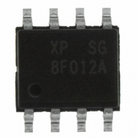
Z8F012ASB020SG Zilog, Z8F012ASB020SG Datasheet - Page 112

Z8F012ASB020SG
Manufacturer Part Number
Z8F012ASB020SG
Description
IC ENCORE XP MCU FLASH 1K 8SOIC
Manufacturer
Zilog
Series
Encore!® XP®r
Datasheet
1.Z8F011ASB020EG.pdf
(282 pages)
Specifications of Z8F012ASB020SG
Core Processor
Z8
Core Size
8-Bit
Speed
20MHz
Connectivity
IrDA, UART/USART
Peripherals
Brown-out Detect/Reset, LED, LVD, POR, PWM, Temp Sensor, WDT
Number Of I /o
6
Program Memory Size
1KB (1K x 8)
Program Memory Type
FLASH
Eeprom Size
16 x 8
Ram Size
256 x 8
Voltage - Supply (vcc/vdd)
2.7 V ~ 3.6 V
Data Converters
A/D 4x10b
Oscillator Type
Internal
Operating Temperature
0°C ~ 70°C
Package / Case
8-SOIC (3.9mm Width)
Processor Series
Z8F012Ax
Core
eZ8
Data Bus Width
8 bit
Data Ram Size
256 B
Interface Type
UART
Maximum Clock Frequency
20 MHz
Number Of Programmable I/os
6
Number Of Timers
2
Operating Supply Voltage
2.7 V to 3.6 V
Maximum Operating Temperature
+ 70 C
Mounting Style
SMD/SMT
Development Tools By Supplier
Z8F04A08100KITG, Z8F04A28100KITG, ZENETSC0100ZACG, ZENETSC0100ZACG, ZUSBOPTSC01ZACG, ZUSBSC00100ZAC, ZUSBSC00100ZACG
Minimum Operating Temperature
0 C
On-chip Adc
10 bit, 4 Channel
Lead Free Status / RoHS Status
Lead free / RoHS Compliant
Other names
269-4039
Z8F012ASB020SG
Z8F012ASB020SG
- Current page: 112 of 282
- Download datasheet (4Mb)
PS022825-0908
Receiving Data using the Polled Method
The UART is now configured for interrupt-driven data transmission. Because the UART
Transmit Data register is empty, an interrupt is generated immediately. When the UART
Transmit interrupt is detected, the associated interrupt service routine (ISR) performs the
following:
1. Write the UART Control 1 register to select the multiprocessor bit for the byte to be
2. Set the Multiprocessor Bit Transmitter (MPBT) if sending an address byte, clear it if
3. Write the data byte to the UART Transmit Data register. The transmitter automatically
4. Clear the UART Transmit interrupt bit in the applicable Interrupt Request register.
5. Execute the IRET instruction to return from the interrupt-service routine and wait for
Follow the steps below to configure the UART for polled data reception:
1. Write to the UART Baud Rate High and Low Byte registers to set an acceptable baud
2. Enable the UART pin functions by configuring the associated GPIO Port pins for
3. Write to the UART Control 1 register to enable MULTIPROCESSOR mode functions,
4. Write to the UART Control 0 register to:
5. Check the RDA bit in the UART Status 0 register to determine if the Receive Data
6. Read data from the UART Receive Data register. If operating in MULTIPROCESSOR
7. Return to
transmitted:
sending a data byte.
transfers the data to the Transmit Shift register and transmits the data.
the Transmit Data register to again become empty.
rate for the incoming data stream.
alternate function operation.
if appropriate.
–
–
register contains a valid data byte (indicated by a 1). If RDA is set to 1 to indicate
available data, continue to
0), continue to monitor the RDA bit awaiting reception of the valid data.
(9-bit) mode, further actions may be required depending on the MULTIPROCESSOR
mode bits MPMD[1:0].
Set the receive enable bit (REN) to enable the UART for data reception
Enable parity, if appropriate and if Multiprocessor mode is not enabled, and select
either even or odd parity.
Step 4
to receive additional data.
Step
5. If the Receive Data register is empty (indicated by a
Universal Asynchronous Receiver/Transmitter
Z8 Encore! XP
Product Specification
®
F082A Series
101
Related parts for Z8F012ASB020SG
Image
Part Number
Description
Manufacturer
Datasheet
Request
R

Part Number:
Description:
Communication Controllers, ZILOG INTELLIGENT PERIPHERAL CONTROLLER (ZIP)
Manufacturer:
Zilog, Inc.
Datasheet:

Part Number:
Description:
KIT DEV FOR Z8 ENCORE 16K TO 64K
Manufacturer:
Zilog
Datasheet:

Part Number:
Description:
KIT DEV Z8 ENCORE XP 28-PIN
Manufacturer:
Zilog
Datasheet:

Part Number:
Description:
DEV KIT FOR Z8 ENCORE 8K/4K
Manufacturer:
Zilog
Datasheet:

Part Number:
Description:
KIT DEV Z8 ENCORE XP 28-PIN
Manufacturer:
Zilog
Datasheet:

Part Number:
Description:
DEV KIT FOR Z8 ENCORE 4K TO 8K
Manufacturer:
Zilog
Datasheet:

Part Number:
Description:
CMOS Z8 microcontroller. ROM 16 Kbytes, RAM 256 bytes, speed 16 MHz, 32 lines I/O, 3.0V to 5.5V
Manufacturer:
Zilog, Inc.
Datasheet:

Part Number:
Description:
Low-cost microcontroller. 512 bytes ROM, 61 bytes RAM, 8 MHz
Manufacturer:
Zilog, Inc.
Datasheet:

Part Number:
Description:
Z8 4K OTP Microcontroller
Manufacturer:
Zilog, Inc.
Datasheet:

Part Number:
Description:
CMOS SUPER8 ROMLESS MCU
Manufacturer:
Zilog, Inc.
Datasheet:

Part Number:
Description:
SL1866 CMOSZ8 OTP Microcontroller
Manufacturer:
Zilog, Inc.
Datasheet:

Part Number:
Description:
SL1866 CMOSZ8 OTP Microcontroller
Manufacturer:
Zilog, Inc.
Datasheet:

Part Number:
Description:
OTP (KB) = 1, RAM = 125, Speed = 12, I/O = 14, 8-bit Timers = 2, Comm Interfaces Other Features = Por, LV Protect, Voltage = 4.5-5.5V
Manufacturer:
Zilog, Inc.
Datasheet:

Part Number:
Description:
Manufacturer:
Zilog, Inc.
Datasheet:


